4600
Elimination of fold-in artefacts for gradient inserts by using the existing whole-body gradient in synergy1University Medical Centre Utrecht, Utrecht, Netherlands, 2Spinoza Center for Neuroimaging, Amsterdam, Netherlands
Synopsis
The short encoding field of a gradient insert makes such a coil susceptible to fold-in artefacts, especially when operated along the z-direction. We propose a method that almost completely eliminates this fold-in artefact by using the whole-body z-gradient as pre-winder and gradient insert (also in z) as readout gradient. This causes signal from outside the linear region of the gradient insert to stay dephased, thus suppressing the signal that folds in. The proposed method is validated and quantified in simulation, and in experiments using a lightweight gradient insert that features a short encoding field.
Background
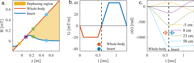
Gradient inserts allow for higher slew rates and gradient strengths than whole-body gradient systems due to their short encoding fields. Such a field is less likely to induce peripheral nerve stimulation (PNS), as the peak field change (dB/dt) produced for the same gradient performance is lower when compared to whole-body gradients 1,2. However, the short encoding field does generate regions outside the imaging region where the field offsets are identical to the field offsets inside the imaging region (Figure 1a), i.e. the mirrored field. This can lead to fold-in artefacts. In particular, gradient inserts operating in the z-direction suffer from these artefacts, due to the presence of anatomy in the mirrored field. Current approaches for this problem are to use confined transmit and receive fields, or shim-fields to suppress the folded-in signal 1,3. However, this does not work when the encoding field is shorter than the range of the transmit and receive fields. In this abstract, we present a method to eliminate almost all fold in artefacts by using a head gradient insert in synergy with the existing whole-body gradient by dephasing the signals of the mirrored field (Figure 1a.).Methods
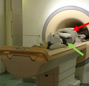
A lightweight (45 kg) single-axis (z-axis) gradient insert was used as 4th physical gradient axis. This coil was designed to be plug-and-play, which means it can be installed in <15 minutes. Combined with an additional gradient amplifier (Prodrive, 940V/630A) this coil produces a maximum slew rate and gradient strength of 1300 T/m/s and 200 mT/m. The 4th gradient axis was controlled using a programmable waveform generated that was triggered by the MR-system. The encoding field of the gradient insert featured a mirrored field at distances >16 cm from the isocenter (Figure 1a). In all experiments, the gradient insert was positioned inside the bore of a Philips Achieva 7T MRI-system and the integrated transmit coil was used for transmit and receive.
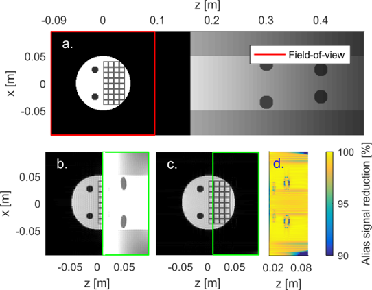
Simulations We simulated two different spatial encoding schemes for the z-direction: Encoding using only the gradient insert, and combined encoding using both gradient coils in synergy. Here, the whole-body gradient was used as pre-winder and the gradient insert as readout gradient (Figure 1b). We simulated the phase accumulation at different spatial positions for this combined operation of both gradient axes (Figure 1c). Furthermore, imaging performance was simulated using a gradient-echo (GRE) sequence with a 2 mm isotropic resolution, a field-of-view of 192 mm, and a readout in the z-direction.
Measurements We placed a spherical phantom filled with saline water in the linear region, and a body phantom and bottles in the mirrored field region (Figure 2). The latter two contained ethylene glycol and mineral oil, respectively. 3D-GRE images were acquired with a 2 mm isotropic resolution, 10 slices, an in-plane field-of-view of 192 mm, and a readout in the z-direction. Three different encoding strategies were used: 1) using only the whole-body gradient, 2) using only the gradient insert, and 3) using a combination of the whole-body and gradient insert.
Results and Discussion
Simulations Figure 1c shows the phase accumulation due to the gradient field at different spatial positions. Here, spins located in the linear region behaved coherently and produced an echo at the same time (Φ = 0). Spins located in the mirrored field region remained de-phased, resulting in a severe reduction of their signal. Figure 3 shows the simulated images. The fold-in artefact is clearly visible when only the gradient insert was used as the readout gradient (Figure 3b). Almost no fold-in was observed when using both the whole-body and gradient insert (Figure 3c). Figure 3d shows the corresponding reduction in aliased signal (mean reduction of 98%).
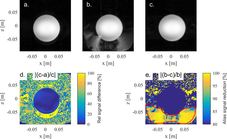
Measurements Figure 4 shows the acquired images using the different encoding strategies. The acquisition using the whole-body gradient yielded no fold-in (Figure 4a), whereas fold-in of the phantom was present when imaging using only the gradient insert for encoding (see Figure 4b). Almost no fold-in was observed when the combination of the whole-body (pre-winder) and gradient insert (readout) was used for encoding (Figure 4cd). In the region of fold-in, this yielded a mean reduction of the aliased signal of 93%, which was in line with simulations (Figure 4e).
Conclusion
In this abstract, we presented a method to eliminate almost all fold-in artefacts when imaging with a gradient insert. This method is applicable to all sequence using a pre-winder and a readout in the z-direction. With this approach, future insert gradient designs can permit more lenient constraints on the size of the gradient coils (smaller, and thus higher efficiency), and the extent of transmit and receive fields.Acknowledgements
No acknowledgement found.References
1. Weiger M, Overweg J, Rösler MB, et al. A high-performance gradient insert for rapid and short-T 2 imaging at full duty cycle. Magn. Reson. Med. [Internet] 2017;00:1–11. doi: 10.1002/mrm.26954.
2. Tan ET, Fiveland E, Park K, Hua Y, Bernstein MA, Iii JH, Shu Y, Foo TK. Development of a Dedicated Asymmetric Head-only Gradient Coil for High-Performance Brain Imaging with a High PNS Threshold. In: Vol. 5177442. ; 2015. p. 5177442.
3. Wiggins C, Caillat M, Bihan D Le et al., 2010, Use of Opposed Shim Currents for Infold Reduction on a UHF MRI System with Head Gradient, ISMRM , #2339
Figures