4598
Non-Cartesian MRI Systems Integrated Development using GPI and MATLAB – A New Rosette Pulse Sequence Example1Biomedical Engineering, Illinois Institute of Technology, Chicago, IL, United States, 2Radiology, The University of Chicago, Chicago, IL, United States, 3Medicine, The University of Chicago, Chicago, IL, United States, 4Philips, Gainesville, FL, United States
Synopsis
The default MRI scanner systems are not equipped with key technical resources for rapid deployment of novel non-Cartesian pulse sequence approaches. Here, we describe a Graphical Programming Interface-based (GPI) platform that is further embedded into the vendor reconstruction environment. This allows for comprehensive development and validation of new trajectories by integrating on-line MRI systems development with off-line resources such as MATLAB, which also enhances trainee-driven research efforts. This tool offers a set of resources including real-time display of MRI k-space and prototyping/characterization of sampling trajectory corrections that may simplify and streamline these non-Cartesian designs.
Background
The technical development of non-Cartesian MRI sampling trajectories is non-trivial, as these approaches often require detailed attention to trajectory optimization, hardware correction, and off-resonance. While more straightforward trajectories such as radial schemes may warrant efficient development with off-line simulation tools only, more complex techniques such as spiral and radial trajectories are more challenging to develop from initial prototypes, validate/correct for imperfections, and clinically translate. Recently, system-embedded tools such as HeartVista’s RTHawk [1] and Graphical Programming Interface (GPI) [2,3] have been integrated into vendor-specific MRI hardware. However, such tools are not yet widely available for non-Cartesian development. Related to this, comprehensive repositories of specialized techniques that support such development are also limited. For instance, the word ‘rosette’ only appears in 3x ISMRM 2018 abstracts by its online search [4]. In this work, we describe an extension of the GPI-based platform that is supported on a major vendor system (Philips, Best, Netherlands). Our tool offers a comprehensive development and validation platform that integrates trainee-driven research primarily conducted off-line with on-line systems development. We thus offer examples of how this platform may effectively facilitate novel non-Cartesian pulse sequence approaches. Using a modified Rosette trajectory based on [5], we offer three specific modular experiment examples that were trivialized and/or streamlined through use of this embedded tool.Materials and Methods
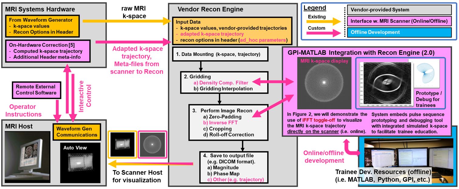
MRI-Embedded Tool Description: Figure 1 shows the extension of the tool that is integrated between the vendor-provided reconstruction engine (Philips Recon 2.0), GPI [2,3], and MATLAB. This integrated tool allows for real-time interrogation of non-Cartesian MRI k-space that may require elaborate correction beyond capabilities of standard off-line (i.e. numerical) simulation.
Proposed Sequence Design Description: A non-Cartesian Rosette trajectory based on a previously provided description by Menon et al. [5] is further described here for development, testing, and validation using this tool. Specifically, the proposed development was: a) provided across different MRI vendors ([5] was completed on Siemens hardware), and b) performed by two technical trainee personnel (one PhD postdoc, and one graduate student) each with no more than three months of non-Cartesian MRI technical development experiences, respectively.
Modular Experiment Descriptions: Three modular experiments were performed using the above tools. First, the extent of gradient imperfection correction [6] step and rotation angle optimization [7] were jointly examined directly on the scanner for the multi-arm Rosette sampling scheme, with the goal of ensuring uniform k-space coverage despite variable acquisition and interleaving conditions. Second, application of sub-lattice shifts in the k-space domain [8] was examined to address Gibbs Ringing. Finally, an in-vivo study was performed to characterize the extent of corrections applied in the first two experiments in phantoms. The embedded tool was deployed on a research 3.0T Philips system; healthy subject heart data was obtained from one highly cooperative volunteer over a prolonged breath-hold. This data was post-processed through the GPI-MATLAB pipeline that yielded additional trajectory information from the scanner hardware.
Results
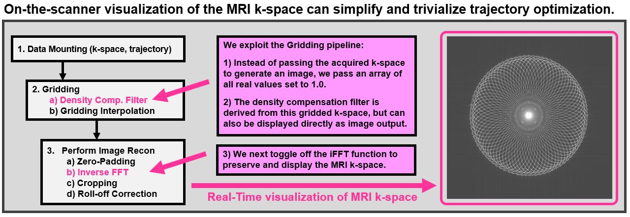
Sampling Trajectory Validation by Simple Visual Inspection: Figure 2 shows an example of our MRI scanner output that display the actual sampling trajectory using a modified online Recon pipeline. This on-the-scanner visualization allows for immediate inspection of the prescribed sampling trajectory directly on the online reconstruction hardware, and eliminates the need for potentially cumbersome off-line post-processing. This non-Cartesian trajectory visualization simplifies the process of pulse sequence parameter optimization that is known to be sensitive to: angulation such as double-oblique prescription, number of interleaves, and other Rosette trajectory design parameters. Also embedded in the platform are utilities that allow for simulation using a numerical phantom for controlled assessment of the obtained trajectory.
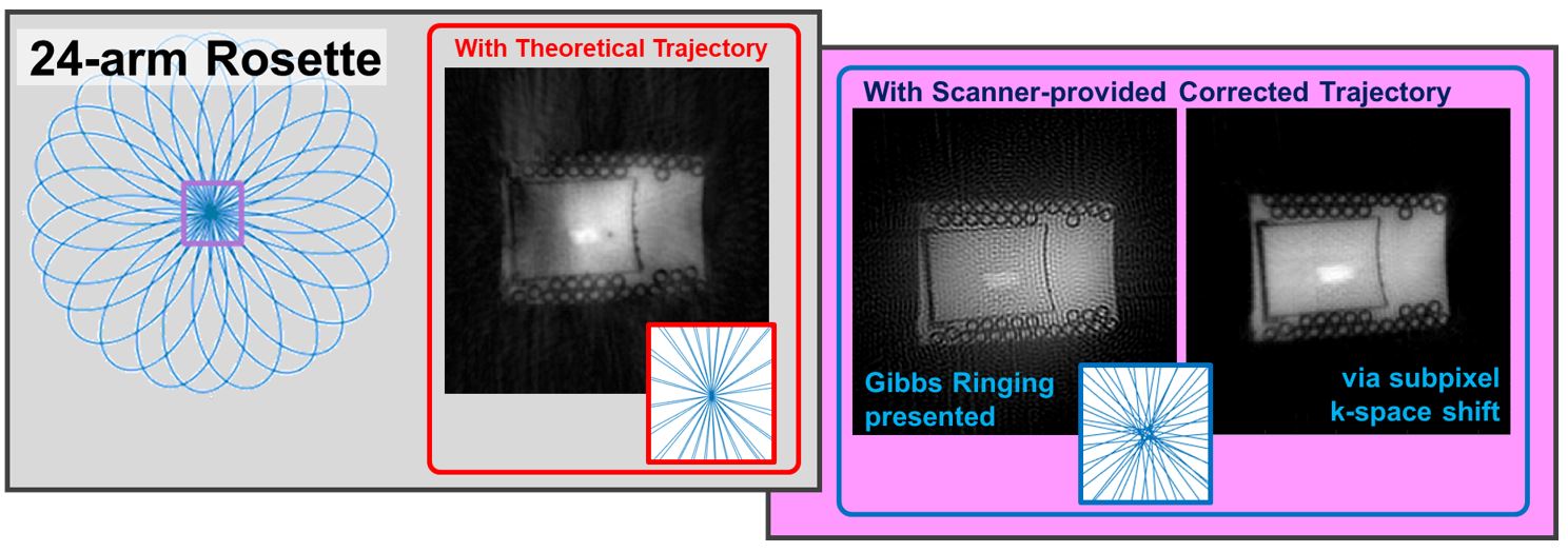
Trajectory and Gibbs Ringing Correction Using a Phantom: Figure 3 demonstrates the MRI-embedded approach associated with trajectory correction. In red, the MRI-computed trajectory (i.e. the look-up table method) that does not account for hardware imperfections and potential distortions in the actual sampling trajectory, is shown. On the right, we show after applying Duyn’s correction [6] (in blue), which allows for both improved visualization of the target phantom whose signal inhomogeneity is less pronounced. Small subpixel shifts in the K-space using both magnitude and relative k-space position can further address Gibbs Ringing [7].
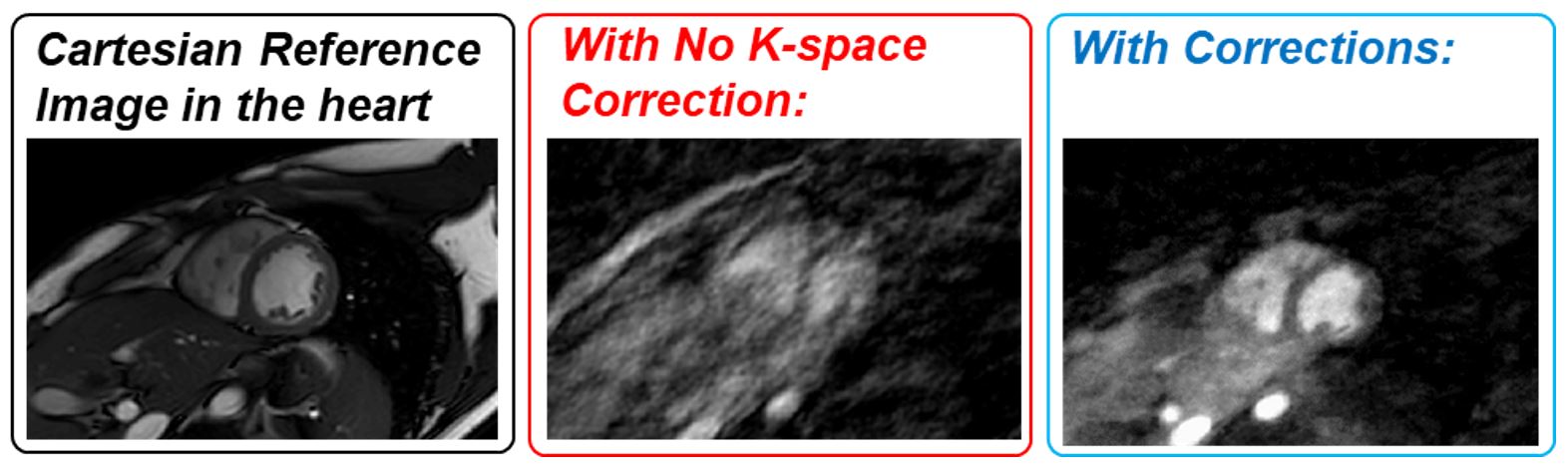
In-vivo Validation: Figure 4 further demonstrates the above corrections re-implemented in-vivo in a dedicated validation experiment. The obtained images clearly show notable differences in the in-vivo image reconstruction.
Discussion
An interactive platform tool with embedded MATLAB and GPI programming on the MRI system may help facilitate non-trivial pulse sequence design in a comprehensive manner. Such integrated system tools can overcome nontrivial challenges associated with sampling trajectory design and corrections. Through immediate display of these designs during MRI experiments, this platform simultaneously serves as an effective education and training tool.Acknowledgements
This work was supported by NIH R01 NS093908 (Carroll, 2016-2018); Illinois Institute of Technology Faculty Innovation Award (Kawaji, 2018); and Philips Seed Grant (Kawaji, 2017).References
1. Santos et al. IEEE EMBS 2004 pp1048.
2. Zwart et al. MRM 74 (5) 1449-1460.
3. Podtar et al. Proc. ISMRM 2018 pp1136.
4. http://indexsmart.mirasmart.com/ISMRM2018/ search term: ‘rosette’. Accessed 2018
5. Menon et al. J. Cerebral Blood Flow & Metabolism 34 (7), 1111-1116 (2014).
6. Duyn et al. Journal of Magnetic Resonance 132, 150-153 (1998).
7. Kawaji et al. PLoS One 2015. e0112020.
8. Kellner et al. MRM 76(5) 1574-1581.
Figures