4508
Coil-induced phase removal during gradient delay estimation1Alltech medical system, Chengdu, China
Synopsis
Gradient delay can lead to severe artifacts in radial imaging. While several methods have been proposed to correct the linear phase caused by gradient delay, no publications have mentioned the impact of coil sensitivity phase during the estimation of gradient delay to our knowledge. This work reports the impact of this factor and presents a simple method to remove the coil-induced phase during the gradient delay estimation. Both phantom and in-vivo test results are provided to demonstrate the effectiveness of this method.
Introduction
Radial imaging has drawn attention over the past years for its applications in UTE, insensitivity to motion, and synergistic combinations with many reconstruction techniques. However, changing the read-out direction every TR in radial acquisition makes it susceptible to gradient delay.
Several methods have been proposed to deal with the gradient delay. One option is measuring or predicting the actual trajectory that the acquisition samples traverse [1,2]. Another option is estimating the gradient delay based on either a cross-correction function [3,4], delay curve fitting [5], or a gradient ellipse model [6]. However, in all of these methods, the impact of coil sensitivity was not taken into consideration or reported, which should not be ignored from our experience. This work shows the coil sensitivity induced phase can affect the gradient delay estimation remarkably and presents a straightforward method to its removal. Both phantom and in vivo results are provided to demonstrate the effectiveness of this method.
Theory and methods
Without loss of generality, we consider a 2D axial case with radial sampling to estimate the timing delay of gradient delay in X and Y axes. It can be easily extend to Z axis by simply switching to a sagittal/coronal plane. The spatial phase of a spoke at projection angle $$$ \theta $$$ in an axial radial scan can be approximated as:
$$\phi\left(\theta,r\right)=\phi_{c}\left(r \right )+r*\phi_{g1}+\phi_{g0}+\phi_{0}(1)$$
where r is the spatial coordinate, $$$\phi_{g1}$$$ is the linear phase dominated by gradient delay, $$$\phi_{g0}$$$ is the gradient induced 0th order phase, $$$\phi_{c}$$$ is the coil induced phase along this projection and $$$\phi_{0}$$$ includes all other contributions that are not caused by gradients or coils such as the field inhomogeneity or receiver phase. If neglected, $$$\phi_{c}$$$may be categorized into the linear term. To completely separate the contribution of $$$\phi_{c}$$$from $$$\phi_{g1}$$$, another spoke is acquired by reverting the read-out gradients. The spatial phase is:
$$\phi\left(\theta,r\right)=\phi_{c}\left(r \right )-r*\phi_{g1}-\phi_{g0}+\phi_{0} (2)$$
Hence, the linear phase caused by the gradient delay can be derived by:
$$\phi_{g1}=\frac{d\left(\frac{\phi\left(\theta\right)-\phi\left(\theta+\pi\right)}{2}\right )}{dr}=\gamma Gt_{d}=\frac{BW}{FOV}*t_{d} (3)$$
Where $$$\gamma $$$ is the gyromagnetic ratio, $$$G$$$ is the readout gradient strength, $$$FOV$$$ is the field- of-view in mm, $$$BW$$$ is the readout bandwidth and $$$t_{d}$$$ is the echo delay of the spoke. In practice, $$$\phi_{g1}$$$ can be derived using a linear fitting process. Assuming $$$N_{c}$$$ coils are present, the process above should be repeated for each coil and an even value for the echo delay is the averaging of the estimation values of all coils.
$$\overline{t_{d}}=\frac{1}{N_{c}}*\sum_{i}^{N_{c}}t_{d}^{i}(4)$$
Where $$$t^{i}_{d}$$$ is the echo delay estimated by i-th coil. The averaging echo delay $$$\overline{t_{d}}$$$ can be related to gradient delay :
$$\overline{t_{d}}=cos^{2}\theta*t_{x}+sin^{2}\theta*t_{y} (5)$$
Where $$$t_{x}$$$ and $$$t_{y}$$$ are delays for the X and Y gradient axis respectively. The whole calibration process needs to be performed only once to set the gradient delay parameter correctly. Experiments were conducted on a 1.5T scanner (Centauri, Alltech Medical Systems, Chengdu, China). A radial sequence was implemented and an eight-channel head coil was used. The gradient delay of each gradient axis was estimated following the procedure above and set back to the scanner. For comparison, gradient delays were also estimated using the built-in procedure, which ignored the impact of the coil induced phase. Calibration scan parameters were: TR=30ms, TE=7ms, spokes=168, BW=250kHz. Both phantom and head images were acquired. Phantom scan parameters: TR=50ms, TE=2.5ms, FOV=300mm*300mm, resolution= 1.2mm*1.2mm, spokes=393, BW=250kHz. In vivo scan parameters: TR=250ms, TE=3ms, FOV=210mm*210mm, resolution=0.8mm*0.8mm, spokes=412, BW=250kHz.
Results
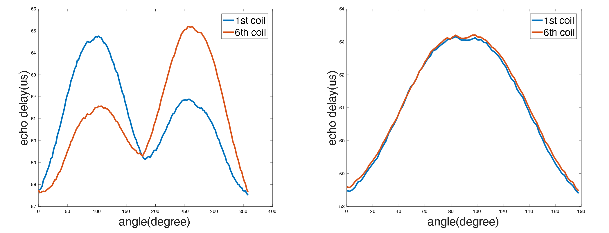
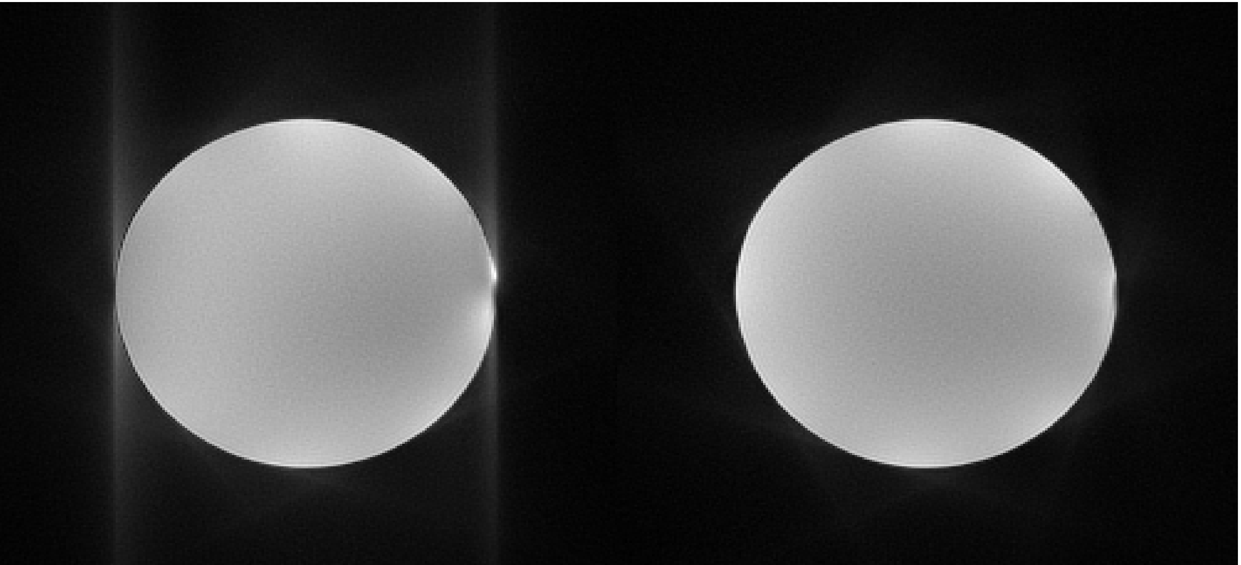
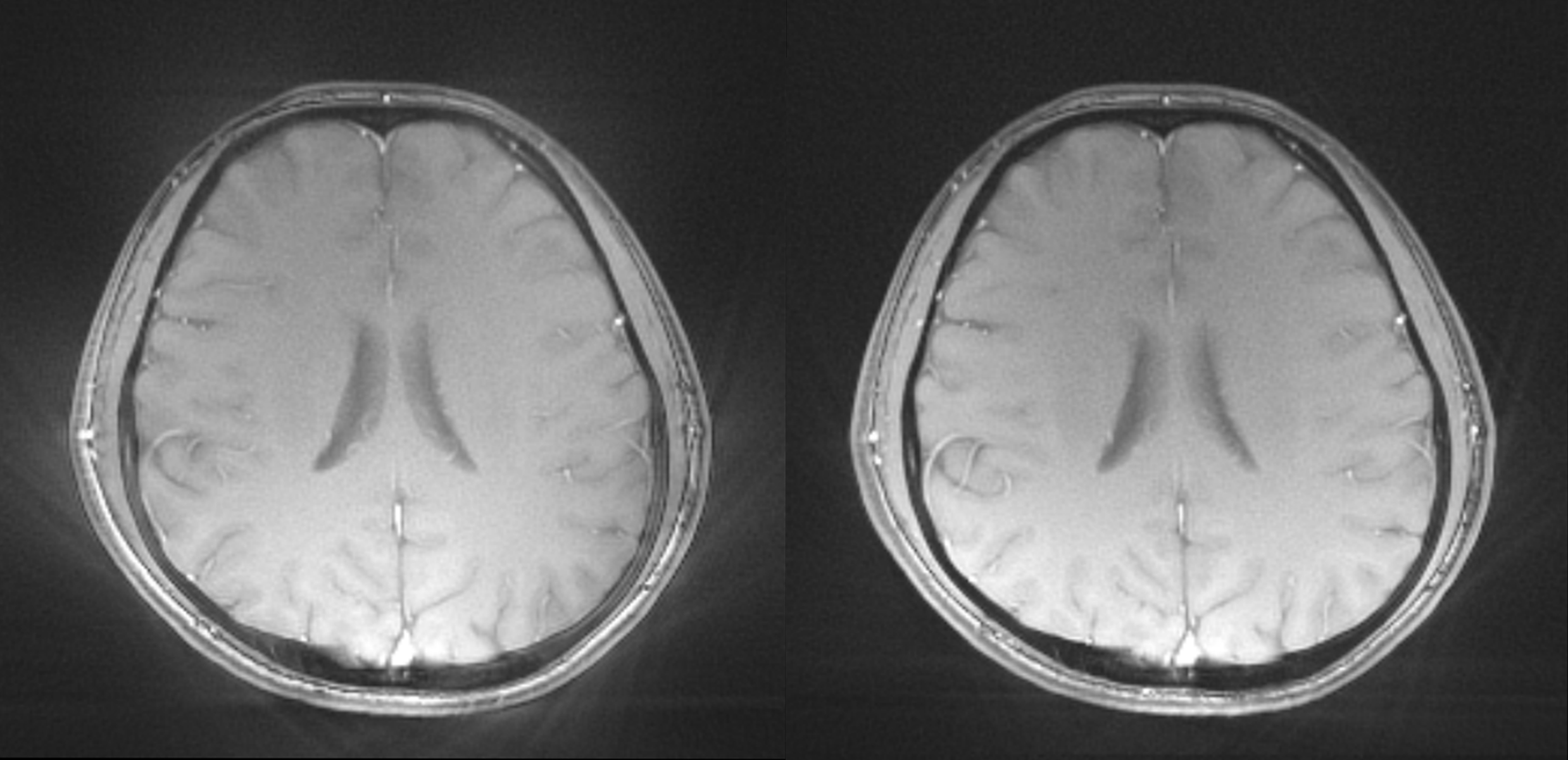
Figure 1 shows the impact of the coil induced phase on the gradient delay estimation. For clarity, only the echo delay curves of the 1st coil and 6th coil are displayed. The delays estimated from the two coils differ significantly. After the proposed calibration, they were well matched. Figure 2 and Figure 3 show the phantom and in vivo results. The artifacts caused by the coil-induced phase were largely removed in both cases.Discussions
In practice, the apparent gradient delay may be affected by the remaining eddy currents. To settle this problem it is recommended to make a fast gradient delay calibration using the real scan parameters. In our experience, 4 pairs of spokes are adequate to determine the gradient delay. Therefore, the impact on pre-scan time is trivial.Conclusions
This work reports the impact of the coil-induced phase on the gradient delay estimation and presents a straightforward method to remove the unwanted phase. Phantom and in vivo imaging results suggest that the proposed method can lead to a more accurate estimation of the gradient delay and reduced artifacts, with negligible impacts on the prescan procedures.Acknowledgements
No acknowledgement found.References
[1] Duyn J H, Yang Y, Frank J A, et al. Simple correction method for k-space trajectory deviations in MRI.[J]. Journal of Magnetic Resonance, 1998, 132(1):150-153.
[2] Addy N O, Wu H H, Nishimura D G. A Simple Method for MR Gradient System Characterization and k-Space Trajectory Estimation[J]. Magnetic Resonance in Medicine, 2012, 68(1):120-129.
[3] Robison R K, Devaraj A, Pipe J G. Fast, simple gradient delay estimation for spiral MRI[J]. Magnetic Resonance in Medicine, 2010, 63(6):1683-1690.
[4] Block KT, Uecker M. Simple method for adaptive gradient-delay compensation in radial MRI. In Proceedings of the 19th Annual Meeting of ISMRM, Montreal, Canada, 2011. p. 2816.
[5] Peters D C, Derbyshire JAMcVeigh E R. Centering the projection reconstruction trajectory: reducing gradient delay errors.[J]. Magnetic Resonance in Medicine Official Journal of the Society of Magnetic Resonance in Medicine, 2003, 50(1):1.
[6] Rosenzweig S, Holme H C M, Uecker M. Simple Auto-Calibrated Gradient Delay Estimation From Few Spokes Using Radial Intersections (RING)[J]. 2018.
Figures