4491
Magnetic tracking of ECG sensors for respiratory motion correction1Université de Lorraine, Nancy, France, 2U1254, INSERM, Nancy, France, 3FHNW/HLS/IMA, FHNW/HLS/IM2, University of Applied Sciences and Arts Northwestern Switzerland FHNW, Muttenz, Switzerland
Synopsis
Monitoring the respiration motion is a crucial step for motion correction. We propose a magnetic tracking system, using a magnetic sensor and a Helmholtz coil as the magnetic field source. By comparing the sensed magnetic fields with theoretical values under the dipole approximation, we were able to locate sensors placed on a subject’s chest and track their motion during breathing. With a sub-centimeter resolution and the current sources of imprecision being identified, we are confident this method can be a viable solution for accurate motion monitoring in MRI, especially by using the magnetic fields generated by the gradient coils.
Introduction
Motion correction is an active field of research for the MRI community. Several techniques have been developed in order to account for motion either in the acquisition process1 or during the image reconstruction2, 3. All motion correction techniques require the acquisition of a motion signal, which can be provided by the MRI signal (MR navigators4,2) or by independent sensors (respiratory belts, accelerometers5, or NMR6). These motion signals are then used either for adjusting the acquisition parameters or integrated in the reconstruction through a motion model. In this paper, we will introduce a new motion sensor based on magnetic tracking. This sensor is already integrated in the ECG sensor for ECG signal denoising7, and there is therefore no additional discomfort for the patient.Purpose
Accurate monitoring of the respiration motion is a crucial step for motion correction. We aimed at estimating the exact position of each sensor in real-time.Methods
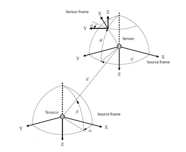
We decided to implement a magnetic tracking, using a magnetic LIS3MDL sensor8, and a three dimensional Helmholtz coil as the magnetic field source9. The position of the sensor is determined by three parameters: the distance d from the source and two angular positions α and β (cf. figure 1). By powering sequentially and synchronously the 3 coils, it was possible to acquire a matrix containing the 9 sensor measurements needed to determine the sensor position. This matrix should then be compared with the theoretically perfect Helmholtz coil magnetic field. To simplify our approach, we approximated our sources by magnetic dipoles whose field can easily be estimated. As the sensor and the source are not in the same frame, it was required to introduce an intermediate frame and express the inputs and the outputs in this same frame in order to link them together. The intermediate frame was chosen so the rotation matrixes involved to go from the source frame to the intermediate frame contain the data position α, β (figure 2). The orientation uncertainty is removed using Kuipers equations10. The distance d is calculated according to the intensity of the sensed magnetic field following an inverse cubic function.Experiments
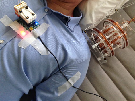
In order to respect the dipole approximation assumption and to accommodate the sensor sensitivity, the sensor had to be placed in a 25-50 cm range from the sources. The source was therefore placed in the gap between the patient’s head and its left shoulder (figure 3) The coils were powered to set a current of approximately 20A. To get a reference position, we used an Optotrack11 device, a motion capture system that uses infra-red signals to detect the position of sensors with a sub-millimeter resolution. The experiments lasted 30 seconds during which the patient was told to breathe deeply. The experiments were run 3 times with slightly different conditions (sensor location and orientation).Results
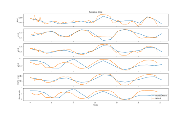
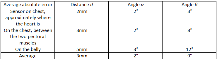
A visual representation of the estimated position of the sensors is depicted in figure 4. Even though the distance and alpha angle are correctly estimated with average differences of 3mm and 2° respectively, differences appear between the estimated and the true beta angles, leading to an inaccurate estimation of the z position of the sensor (>1cm). It has to be noted that the further the sensor is from the source, the less accurate the estimation, which could be explained by the sensitivity of the magnetic sensor.Discussion
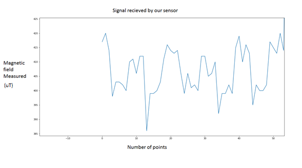
Our system show encouraging similarities with a clear periodical pattern but still lacks accuracy, with errors over 1 cm in the z direction. Several factors can account for this difference, the most important one being the imperfection of the source. The coils were powered by a voltage source and thus were not powered with the exact same current intensity. Furthermore, the current intensity delivered by the source was not constant through time and the signals measured were not shaped as expected (figure 5). A real current source providing the same constant current intensity to every coil could improve the results. An alternative approach would be to map the source magnetic field in the area of interest to get rid of the dipolar approximation, and improve the sensor tracking accuracy12. Finally, we are also investigating the possibility of using the magnetic fields generated by the gradient coils directly, thus ensuring a practical use of this sensor tracking during imaging without interference.Conclusion
This study has shown that it should be possible to use magnetic tracking for accurate estimation of motion. We are positive about this approach being a viable solution for motion correction in MRI, especially by using the magnetic field generated by the gradient coils.Acknowledgements
The authors would like to acknowledge the Region Grand Est and the Doctoral School "IAEM" from the Université de Lorraine for funding Benjamin Roussel's PhD.References
[1] White, et al. "PROMO: real‐time prospective motion correction in MRI using image‐based tracking." Magnetic Resonance in Medicine: An Official Journal of the International Society for Magnetic Resonance in Medicine 63.1 (2010): 91-105.
[2] Pipe, "Motion correction with PROPELLER MRI: application to head motion and free‐breathing cardiac imaging." Magnetic Resonance in Medicine: An Official Journal of the International Society for Magnetic Resonance in Medicine 42.5 (1999): 963-969.
[3] Odille, Freddy, et al. "Generalized reconstruction by inversion of coupled systems (GRICS) applied to free‐breathing MRI." Magnetic Resonance in Medicine: An Official Journal of the International Society for Magnetic Resonance in Medicine60.1 (2008): 146-157.
[4] Sachs, Todd S., et al. "Real‐time motion detection in spiral MRI using navigators." Magnetic resonance in medicine 32.5 (1994): 639-645.
[5] Chen, et al. "Design and validation of a novel MR-compatible sensor for respiratory motion modeling and correction." IEEE Transactions on Biomedical Engineering 64.1 (2017): 123-133.
[6] Aranovitch, et al. "Prospective motion correction with NMR markers using only native sequence elements." Magnetic resonance in medicine 79.4 (2018): 2046-2056.
[7] Felblinger, et al. "Smart MR ECG sensor for sequence synchronization and patient monitoring." IRBM 32.3 (2011): 179-184.
[8] https://www.st.com/content/ccc/resource/technical/document/datasheet/54/2a/85/76/e3/97/42/18/DM00075867.pdf/files/DM00075867.pdf/jcr:content/translations/en.DM00075867.pdf
[9] Raab, F. H., Blood, E. B., Steiner, T. O., & Jones, H. R. (1979). “Magnetic position and orientation tracking system. IEEE Transactions on Aerospace and Electronic systems”, (5), 709-718.
[10] Kuipers, J. B. (1980). “SPASYN-an electromagnetic relative position and orientation tracking system.” IEEE Transactions on Instrumentation and Measurement, 29(4), 462-466.
[11] https://www.ndigital.com/msci/products/optotrak-certus/
[12] PASCAL, Joris, VOGEL, Dorian, KNECHT, Sven, et al. Three-dimensional Magnetic Camera for the Characterization of Magnetic Manipulation Instrumentation Systems for Electrophysiology Procedures. In : EMBEC & NBC 2017. Springer, Singapore, 2017. p. 410-413.
Figures