4457
Exploring the sensitivity of Magnetic Resonance Fingerprinting to k-space trajectory uncertainties1Information Engineering, University of Padova, Padova, Italy, 2Padova Neuroscience Center, Padova, Italy, 3Center for Advanced Imaging Innovation and Research (CAI2R), New York, NY, United States, 4Bernard and Irene Schwartz Center for Biomedical Imaging, New York, NY, United States, 5New York University School of Medicine, The Sackler Institute of Graduate Biomedical Sciences, New York, NY, United States
Synopsis
In this work, we experimentally explore the sensitivity of Magnetic Resonance Fingerprinting (MRF) to k-space trajectory uncertainties typically encountered in non-cartesian imaging. We demonstrate that T1 and T2* quantification can be affected by minor gradient delays observed in stack-of-stars 3D MRF implementations, particularly resulting in severely disrupted T2* measures. As a first approximation, we modeled these imperfections as constant readout sampling shifts of a few integer k-space steps along every trajectory direction. We show that by simply shifting back the nominal sampling locations before the reconstruction can restore reliable MRF parametric estimates.
Introduction
Magnetic Resonance Fingerprinting (MRF)1 provides an attractive means for fast and robust relaxation mapping2. Its speed depends on incoherent k-space under-sampling, which could be achieved, for example, by using non-cartesian readouts (e.g. spiral1, or radial2). However, these readouts require high-fidelity gradient control. In this work, we explore the sensitivity of MRF-derived relaxation to the k-space trajectory uncertainties typically encountered using a radial sampling strategy. We also provide a simple correction strategy that largely restore the accuracy of parametric estimates.Methods
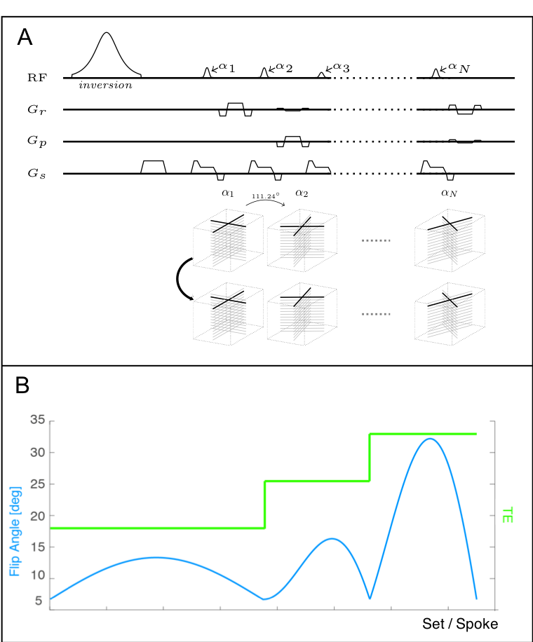
Sequence design: Two MRF implementations were evaluated (Fig. 1), both based on a 3D stack-of-stars readout (2 spokes/star, golden angle increment3). The first (MRF3D), estimates T1, B1+ as described by Fujimoto et al4. The second (MRF3D-vTE), was derived from the first by varying the echo time in fixed incremental steps to simultaneously measure T2* (Fig. 1-B). The underlying pulse sequence consists in an adiabatic non-selective inversion followed by 750 spoiled excitations, with variable Flip-Angle (FA) pattern (Fig. 1-B).
MRF Reconstruction: MRF data was reconstructed in Matlab (MathWorks, MA, USA) using Fessler’s NUFFT5 toolkit as in Fujimoto et al4. The TE-independent phase-offset (i.e., the transmit/receive phase) was removed using a separate set of coil sensitivities for each TE-section6. An MRF dictionary was created using the Extended Phase Graph7 approach and matched to the experimental fingerprints by maximum inner product.
Trajectory correction: We assumed that, as a first order approximation, trajectory imperfections can be described as shifts along the sampling direction8. For simplicity, but without loss of generality, we have considered only integer steps (fixed readout bandwidth).
Experimental setting: The MRF3D-vTE implementation was first validated on phantom. Subsequently, both the MRF3D (M0,T1, B1+) and MRF3D-vTE (M0, T1, B1+, T2*) were used along with standard morphologic pulse sequences over two healthy volunteers. All experiments were performed on a MAGNETOM 7T (Siemens Healthineers, Erlangen, Germany) using a 1TX-32RX head coil (Nova Medical, Wilmington, MA, USA). The study was approved by our local institutional review board.
Results & Discussion
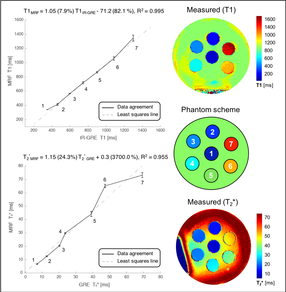
Figure 2 (top) shows the high level of agreement achieved between the T1 measured using the MRF-vTE and a gold standard reference scan (series of inversion-recovery spin-echo measurements). A similar agreement was observed when comparing the observed T2* to estimates derived from a multi-echo gradient-echo (ME-GRE) measurement (Fig. 2, bottom).
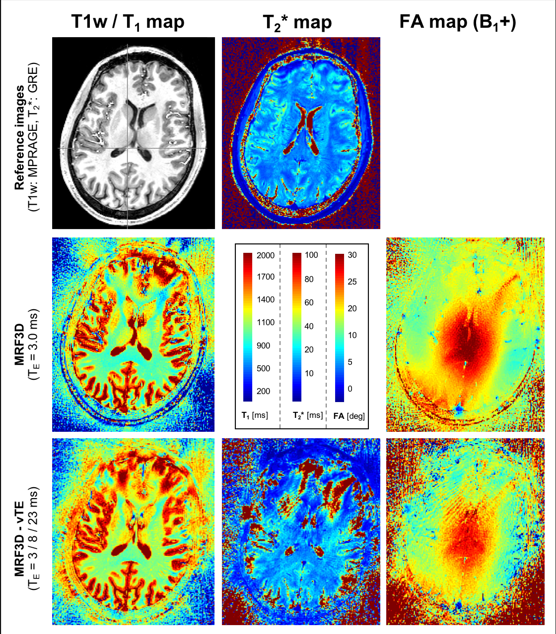
Figure 3 shows the MRF estimates together with a reference T1-w and T2* map (as from ME-GRE) in one volunteer. T1 estimates were geometrically consistent with the T1-w image (Fig. 3, top-left) across posterior brain areas, but were severely distorted frontally (Fig. 3, left column), with non-physiologic apparent T1 values with both MRF implementations. Quantitative T2* measures exhibited a relatively viable tissue contrast across middle/posterior brain areas (high B1+), but the same frontal distortion pattern of T1 maps (Fig. 3, middle column). Since these effects are observed in both MRF implementations, the T2* encoding is unlikely to be the cause of these artifacts. At the same time, they cannot be explained by the measured B1+ (Fig. 3, right column), which appears to be adequate for T1 quantification3,9.
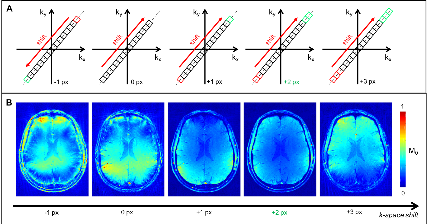
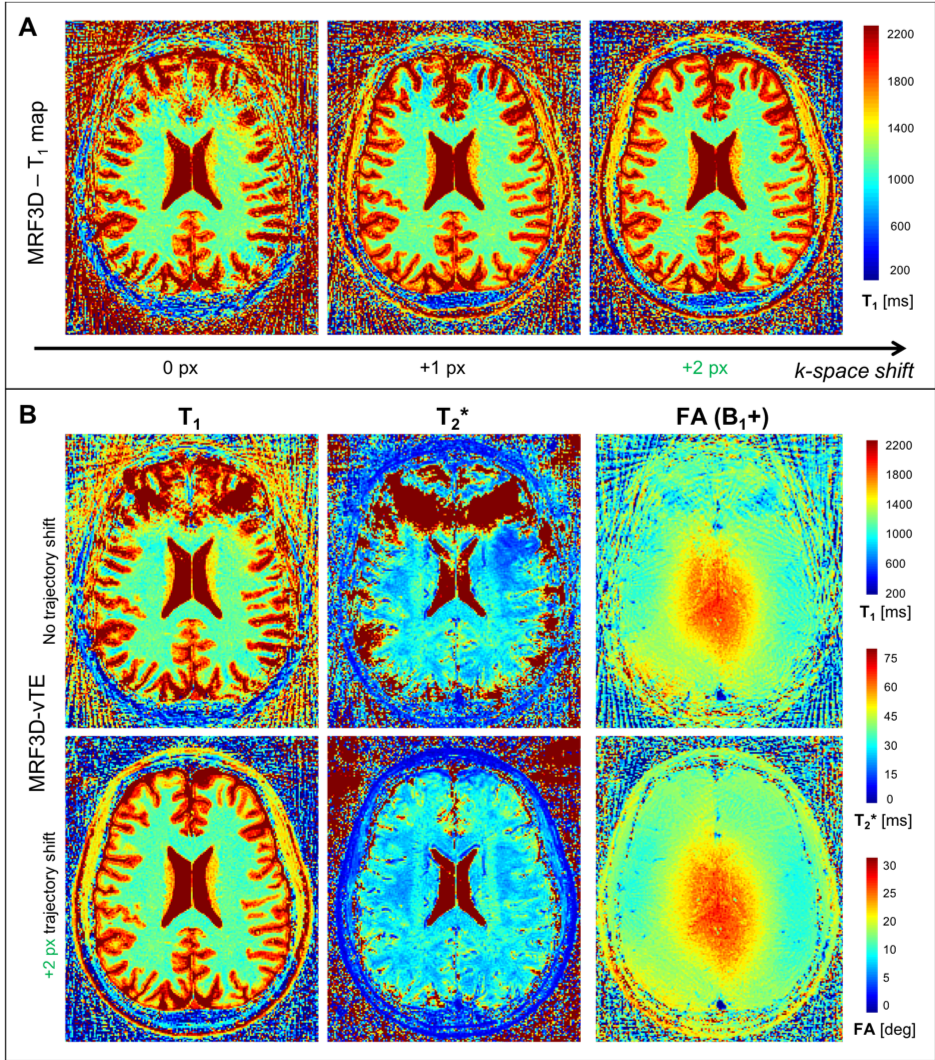
Reconstructing the MRF3D with various k-space shifts (Fig. 4-A) resulted in the M0 maps of Fig. 4-B. Less or equal than zero shifts resulted in atypical M0 maps with visual artifacts. Positive shifts, on the other hand, progressively restored the expected M0 pattern (peaking at +2 px). Note that, under our prescribed settings, a +2 px shift corresponds to an 8.2 μs delay, less than the typical gradient raster time of the scanner (10 μs), suggesting that the observed artifacts cannot be attributed to extensive gradient mis-calibrations or eddy-currents, but rather to small synchronization imperfections between ADC and gradient events.
Figure 5 shows the effect of adding positive k-space shifts (+2 px) on the MRF parametric maps. Both MRF implementations resulted in large improvements over the frontal brain region, particularly evident in the T2* maps (Fig.5-B, middle column), where the k-space shifts recovered a consistent anatomical structure. Considering the impact of such first-order corrections, even higher robustness may be enabled with higher order schemes, for example accounting for readout uncertainties not necessarily fixed along the fingerprint (i.e., variable at single-shot level).
Conclusions
In this study, we investigated the sensitivity of MRF to 3D k-space trajectory uncertainties. We demonstrated that even a minor gradient delay can severely affect the T1 and T2* estimates in a high-resolution stack-of-stars based MRF sequence. Delaying the nominal radial trajectories by integer k-space steps along each spoke direction can provide a simple means to restore the accuracy of the parameter maps.
Acknowledgements
This work was supported in part by NIH R01 AR070297 and NIH R21 EB020096, and it was performed under the rubric of the Center for Advanced Imaging Innovation and Research (CAI2R, www.cai2r.net), a NIBIB Biomedical Technology Resource Center (NIH P41 EB017183).References
1. Ma, D., Gulani, V., Seiberlich, N., Liu, K., Sunshine, J. L., Duerk, J. L., & Griswold, M. A., Magnetic resonance fingerprinting. Nature, 495(7440), 187-192 (2013).
2. Cloos, M. A., Knoll, F., Zhao, T., Block, K. T., Bruno, M., Wiggins, G. C., & Sodickson, D. K. (2016). Multiparametric imaging with heterogeneous radiofrequency fields. Nature Communications, 16;7:12445.
3. Winkelmann, S., Schaeffter,T., Koehler,T., Eggers, H. & Doessel, O. An Optimal Radial Profile Order Based on the Golden Ratio for Time-Resolved MRI. IEEE Transactions on Medical Imaging, 26(1):68–76 (2007).
4. Fujimoto, K., Cloos, M.A., Urushibata, Y., Okada, T., Cortical T1 mapping with 3D MR Fingerprinting at 7T using a single transmit channel. In the Proceedings of the 26th Annual Meeting of the ISMRM, Paris, France, 2018, n1135.
5. Fessler, J.A., On NUFFT-based gridding for non-Cartesian MRI. Journal of Magnetic Resonance 188 (2007) 191–1956.
6. Lattanzi, R., Zhang, B., Knoll, F., Assländer, J., Cloos, M.A., Phase unwinding for dictionary compression with multiple channel transmission in magnetic resonance fingerprinting. MRI. 2018 Jun; 49:32-38.
7. Weigel, M., Extended phase graphs: Dephasing, RF pulses, and echoes - Pure and simple. Journal of Magnetic Resonance Imaging, 41(2), 266–295.
8. Block et al., Towards routine clinical use of radial stack-of-stars 3D gradient-echo sequences for reducing motion sensitivity. JKAMRM 2014;18:87-106
9. Paška, J., Cloos, M.A., Wiggins, G.C., A rigid, stand-off hybrid dipole, and birdcage coil array for 7 T body imaging. Magn Reson Med. 2018 Aug;80(2):822-832.
Figures