4445
Motion correction in Brain MR imaging using a Structure Light based Optical MOtion Tracking system (SLOMO)1School of Medicine, Tsinghua University, Beijing, China, 2School of Biomedical Engineering and Imaging Sciences, King's College London, London, United Kingdom, 3Vascular Imaging Laboratory, Department of Radiology, University of Washington, Seattle, WA, United States
Synopsis
Motion artifact is an important challenge in MR imaging. Optical tracking based motion correction technique has been verified effective with the advantages of perfect accuracy, real-time performance and no effect on sequence and scan time. However, most traditional system need an additional Reflective Marker to trace and quantify the motion parameters, which complicated the scan procedure. Recently, our group proposed a markerless optical tracking solution(NORMS) and validated its ability in non-rigid motion detection and correction for carotid artery imaging. In this study, we aim to develop a parallel line Structure Light based Optical Motion Tracking system (SLOMO) to accurately correct rigid motion by acquiring the whole 3D surface. The results demonstrated the feasibility of SLOMO system in motion correction for brain imaging.
Introduction
Motion artifact is an important challenge in MR imaging. Optical tracking based motion correction technique has been verified effective with the advantages of perfect accuracy, real-time performance and no effect on sequence and scan time2. However, most traditional system need an additional Reflective Marker1 to trace and quantify the motion parameters, which complicated the scan procedure. Recently, our group proposed a markerless optical tracking solution (NORMS)6 and validated its ability in non-rigid motion detection and correction for carotid artery imaging. In this study, we aim to develop a parallel line Structure Light based Optical Motion Tracking system (SLOMO) to accurately correct rigid motion by acquiring the whole 3D surface. The results demonstrated the feasibility of SLOMO system in motion correction for brain imaging.Method and materials
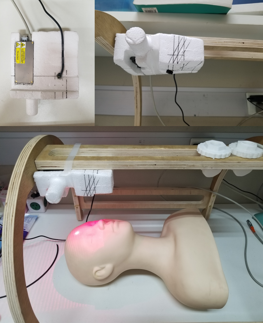
SLOMO system
The SLOMO system consist of a MR compatible high-speed camera (250Hz,
MRC, Germany) and a parallel-line laser (41 parallel lines). The paired camera-laser
system was pre-calibrated and fixed by a home-designed holder (as shown in Fig.
1) and was mounted on a wooden frame (Fig. 1).The optical scheme of the system
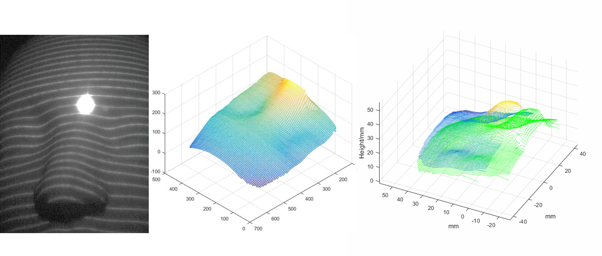
is shown in Fig 1.The captured optical images were processed to reconstruct a point
cloud of the measured 3D surfaces using the triangulation measurement. Then the
transformation matrixes were extracted among different phases using combined PPF3 (Point Pair Feature) and ICP4 (Iterative Closest Point) algorithm (Fig 2).
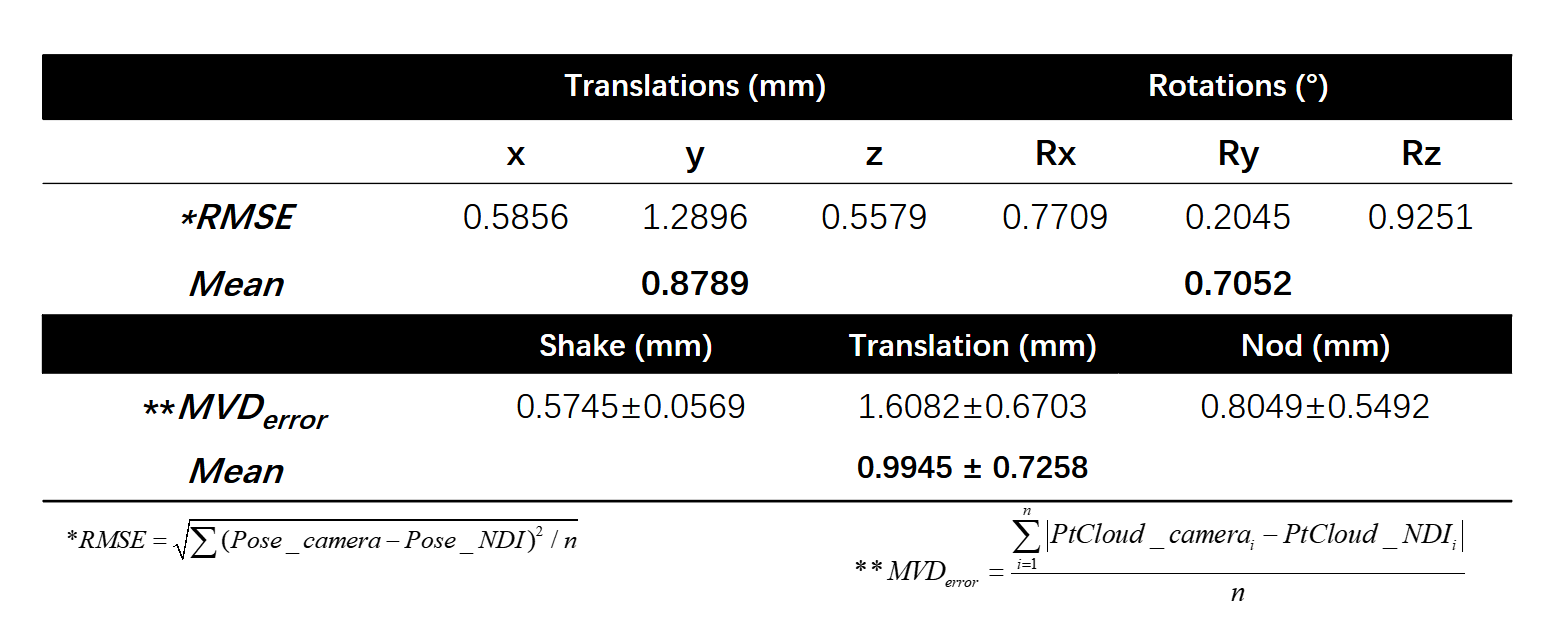
Before in vivo experiment, the accuracy of the SLOMO system were tested on a
dummy compared with NDI equipment (Polaris Series, Canada) after
cross-calibration(Table 1).
Image acquisition and motion correction
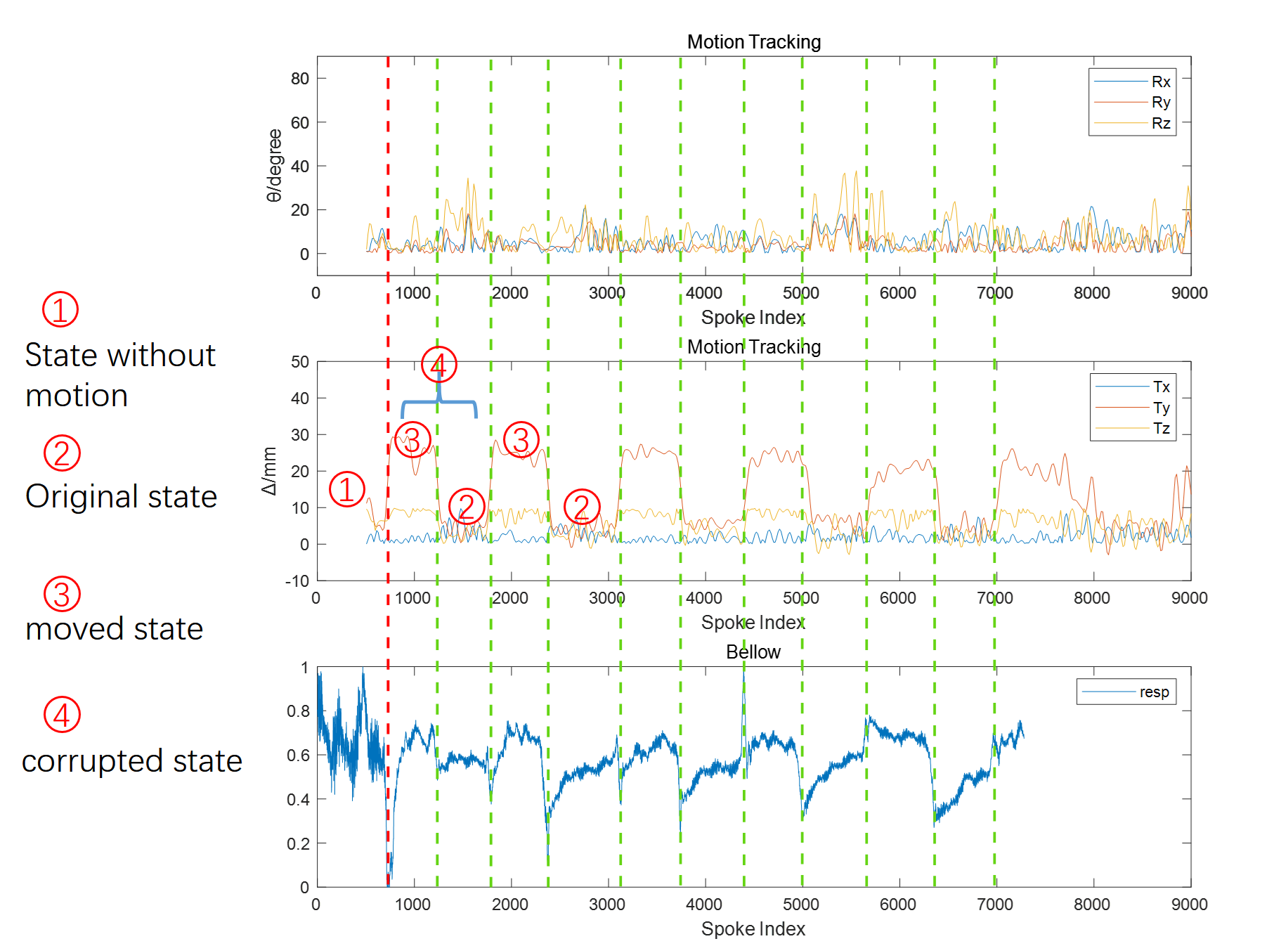
The SLOMO system was installed on a Philips Achieva TX 3.0T scanner (Philips, Best, The Netherlands) with an 8-channel head coil. A 2D FFE sequence with trajectory of Golden Angle Radial sampling was used to image the brain with scan parameters: TR/TE, 7.6/3.0ms; in-plane resolution, 1.25×1.25mm2; slice thickness, 5mm; flip angle, 15°; FOV, 320×320mm2; sampling density, 3000%; acquisition time, 57s. A bellow was placed under the subject’s head to detect and synchronize the initial motion point. Once acquisition got started, subject was instructed to perform periodic head yawing from side to side with the amplitude of about 3cm, followed by 5-second rest state without motion, and continue this maneuver for the whole scan. Optical tracking results were recorded and implemented to synchronize the MR and SLOMO system by the measurement of bellow (Fig 3). Then, each transformation matrix can be assigned to each acquisition spoke, which can be clustered into bins according to the transform matrix for image reconstruction. 768 spokes (300% sampling) were selected evenly from no-motion state (still state before subject was instructed to move), original state (state when subject move back to the original position) and moved state (state when subject moved his head to the left side) respectively to construct images using NUFFT
Results
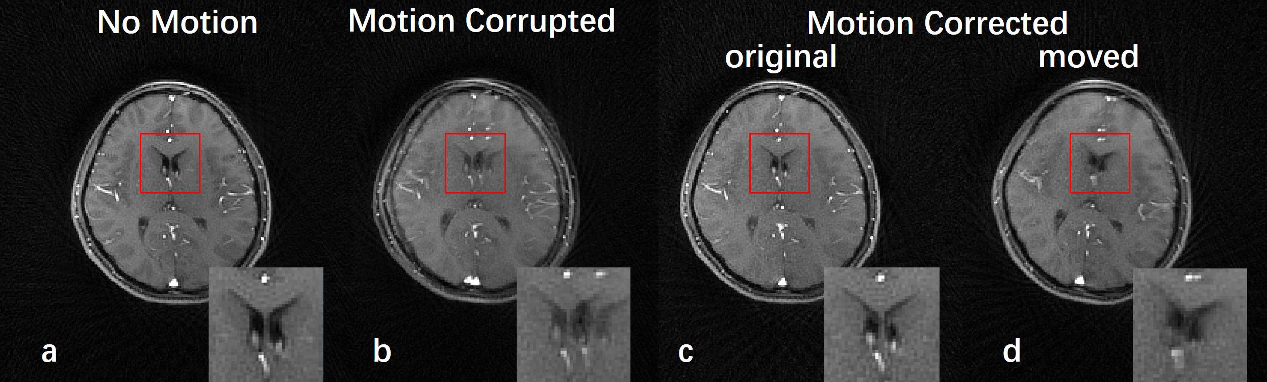
In the dummy experiment, the RMSE of pose detection is 0.88mm in translation degree and 0.71° in rotation degree between SLOMO and NDI system (Table 1). The MVD3 (mean vector displacement) taken to assess the accuracy of point cloud registration is 0.9945(±0.7258) mm (Table 1), Note, the position detection precision of the NDI system was reported to be less than 0.3mm. In the in-vivo imaging, the SLOMO system successfully detect the motion of patients, which is majorly the translation in the y and z directions (Ty and Tz), which can be well aligned with the periods of the measurement of bellow under the head (Fig 3). Fig 4 shows the reconstructed images. Image from state without motion(Fig 3(1)) presents the best sharpness and the highest parenchyma contrast (Fig 4a). motion-corrupted image(Fig 3(4)) suffers the severe blurring and the distinct overlapped artifacts from two states (Fig 4b). Image reconstructed from original state(Fig 3(2)) presented comparable anatomical sharpness and contrast (Fig 4c), whereas the result from moved state(Fig 3(3)) has much better image quality than the corrupted state, but a little lower than the no-motion state (Fig 4d) for the probable reason that subject can hardly move to the same position every time.Discussion and conclusion
This study proposes a MRI motion correction solution: SLOMO and demonstrated its feasibility in brain MRI imaging. The dummy experiment showed that the SLOMO system have high measurement accuracy. The in vivo experiment suggest it can be used in MR scan to correct the motion. Similar to previous proposed NORMS system, the SLOMO system also can be used to other non-rigid motion correction, such as liver and neck imaging corrupted by coughing, swallowing and respiration. Future studies will improve the optical scheme to better avoid the shadowing of coils to achive higher accuracy and efficiency .Acknowledgements
No acknowledgement found.References
1. Zaitsev M, Dold C, Sakas G, Hennig J, Speck O. Magnetic resonance imaging of freely moving objects: prospective real-time motion correction using an external optical motion tracking system. Neuroimage 2006;31:1038–1050.
2. Maclaren J, Herbst M, Speck O, Zaitsev M. Prospective motion correction in brain imaging: a review. Magn Reson Med 2013;69:621–636.
3. Drost B , Ulrich M , Navab N , et al. Model globally, match locally: Efficient and robust 3D object recognition. Computer Vision & Pattern Recognition. IEEE, 2010.
4. Chen, Y. and G. Medioni. “Object Modelling by Registration of Multiple Range Images.” Image Vision Computing. Butterworth-Heinemann . Vol. 10, Issue 3, April 1992, pp. 145-155.
5. Maclaren J , Aksoy M , Ooi M B , et al. Prospective motion correction using coil‐mounted cameras: Cross‐calibration considerations[J]. Magn Reson Med. 2018;79(4):1911-1921
6. Chen Zhang, Jin Liu, Jinnan Wang, Jiarui Cai, Chun Yuan, and Huijun Chen, Detection Arterial Pulsation Using Non-attached Optical Remote Motion Sensing (NORMS) System: a preliminary study; The 5th International Congress on Magnetic Resonance Imaging & 22nd Annual Scientific Meeting of KSMRM, Grand Hilton Hotel, Seoul, Korea, 3.23-3.25; 2017
Figures