4363
Evaluation of attenuation reduction of a dedicated carotid PET/MRI coil1Radiology and Nuclear Medicine, Maastricht University Medical Center, Maastricht, Netherlands, 2CARIM School for Cardiovascular Diseases, Maastricht, Netherlands, 3Machnet B.V, Roden, Netherlands
Synopsis
Dedicated RF coils are required to acquire high
resolution MR images. These RF coils are in the PET field of view in a PET/MRI
scanner. Therefore, attenuation from these coils can cause bias in PET
quantification. This study compares a newly developed dedicated PET/MRI RF coil
with a coil designed for MRI-only. Both a phantom and patients injected with 18F-FDG were scanned with both coils and without a dedicated
coil (baseline). Activity measured in the phantom was significantly reduced
with the MRI-only coil compared to the new coil, which did not show any significant attenuation effect. Results in patients support this finding.
Introduction
Dedicated carotid radiofrequency (RF) coils allow high resolution carotid vessel wall imaging.[i] An RF MRI coil introduces attenuation, which can result in a bias in PET quantification.[ii] One method to correct for the attenuation is to create an attenuation map for the coil based on CT images, however this is complex for surface coils.[iii] The method we present is to use a dedicated PET-lucent RF coil. In this study, we compare the performance of a newly developed dedicated PET/MRI carotid coil against an original model designed for MRI-only use, in a phantom and patient study.Methods
A 3.0T Siemens Biograph mMR PET/MRI scanner was used to test the performance of the different coils in a phantom and in patients. The coils under investigation were the PACC-SB30 (PET/MRI coil) and PACC-ST30 (MRI-only coil), i.e. 4-channel bilateral carotid coils (Machnet BV, Roden, The Netherlands).
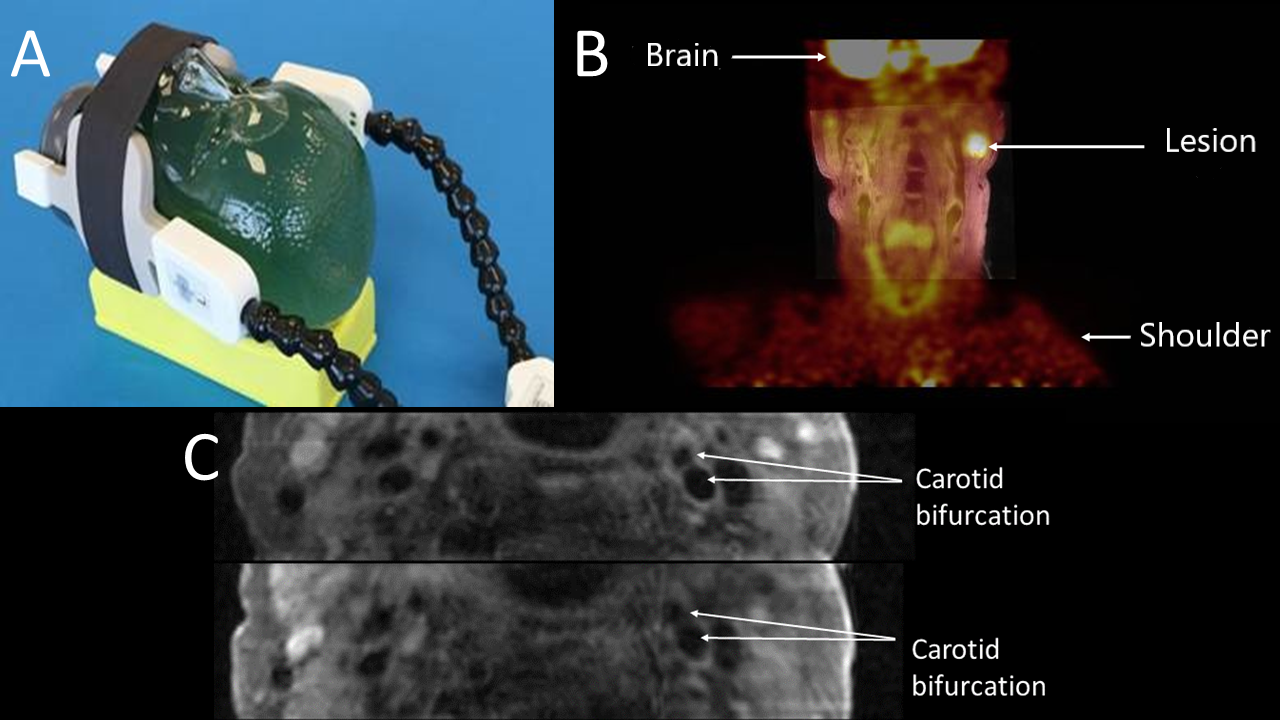
Phantom Study: A 14-cm-diameter cylindrical phantom filled with an aqueous solution of 18F-fluordeoxyglucose (18F-FDG) was scanned without dedicated coils (baseline), then with the PET/MRI coil (Figure 1A) and finally with the MRI-only coil. Acquisition time was adjusted for the amount of radioactive decay. A CT attenuation map of the phantom was manually co-registered to the images to generate attenuation corrected PET reconstructions (without correcting for coils). Regions of interest (ROIs) were drawn (2 cm diameter) in each transversal 2 mm PET slice at the average position of the carotid artery relative to the coil. The decay-corrected normalized activity (in %) was calculated and compared with baseline values.
Patient Studies: Three patients scheduled to receive 2MBq/kg activity of 18F-FDG for a clinical examination volunteered for this study. The study was approved by the local ethics committee and all patients provided written informed consent. Directly following the clinical exam, patients were subsequently scanned for 10 minutes with the PET/MRI coil, the MRI-only coil and without a dedicated coil. Attenuation maps were generated using only the body coil to ensure that the same correction is performed in all configurations and differences on the PET image are caused by attenuation from the coil under investigation. ROIs were drawn on both left and right carotid arteries on the fused PET/MRI images adjacent to the center of the coil and the mean standardized uptake values (SUVmean) were compared. One-way ANOVA was performed to check for significant difference between the mean values from the coils followed by post hoc test (Tukey HSD) to check for significant difference between each of the coils. The SUVmax of a lesion (Figure 1B) in a patient with oropharyngeal cancer was also compared.
Results
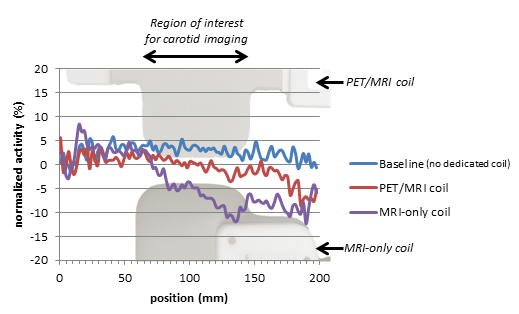
Phantom Study: Figure 2 shows a graphical representation of the normalized activity as a function of longitudinal position (i.e. adjoining transversal PET slices). The PET/MRI coil demonstrates only a slight decrease (3-4%, at the order of scan-rescan variation) at the position of the coil. The MRI-only coil shows a more substantial decrease (up-to 10%) in this region. In contrast with the MRI-only coil, the signal loss of the dedicated PET/MRI coil at the electronic housing is outside the region that would normally be imaged with the coil.
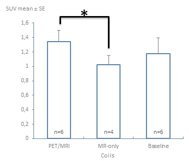
Patient Studies: The SUVmean (mean ± standard error) were 1.34±0.15 for the PET/MRI coil (n=6), 1.03±0.13 (n=4) for MRI-only and 1.17±0.22 (n=6) for baseline (no dedicated coil). The SUVs acquired with the PET/MRI coil were significantly higher than with the MRI-only coil (p=0.039) (Figure 3). SUVs of the other configurations were not significantly different. The SUVmax of the lesion visible in a patient with oropharyngeal cancer acquired with the PET/MRI coil was 6.1, while 5.8 without a dedicated coil.
Discussion
The phantom experiments showed that the difference between the SUV with the PET/MRI coil and baseline is less than 4% in the region of interest, while a more pronounced decrease in the SUV is observed with the MRI-only coil. In the patient studies, a non-significantly different SUV for the PET/MRI coil compared to baseline is in-line with the phantom results. A significantly lower SUV observed with the MRI-only coil in comparison to the PET/MRI coil demonstrates that significant attenuation effects are resolved by the PET-lucent design. The non-significant difference between the MRI-only coil and the baseline SUV values in the patients may be due to the low sample size.Conclusion
The phantom study clearly demonstrates less attenuation by the dedicated PET/MRI coil as compared to the MRI-only coil which is within scan-rescan variation of PET. Initial data from three patients shows similar findings.Acknowledgements
This project has received funding from the European Union (EU) Horizon 2020 research and innovation program under the Marie Skłodowska- Curie grant agreement No. 722609 and from Stichting de Weijerhorst.References
- Saba, L., et al. (2018). "Carotid Artery Wall Imaging: Perspective and Guidelines from the ASNR Vessel Wall Imaging Study Group and Expert Consensus Recommendations of the American Society of Neuroradiology." AJNR Am J Neuroradiol 39(2): E9-E31.
- G Delso, A. M.-M., R A Bundschuh, R Ladebeck, Y Candidus, D Faul, S I Ziegler (2010). "Evaluation of the attenuation properties of MR equipment for its use in a whole-body PET/MR scanner." PHYSICS IN MEDICINE AND BIOLOGY: 4361–4374
- Mootaz Eldib, Jason B., Philip M Robson, Claudia Calcagno, David D Faul, Charalampos Tsoumpas, Zahi A Fayad (2015). "Markerless attenuation correction for carotid MRI surface receiver coils in combined PET/MR imaging." Physics in Medicine & Biology: 4705–4717
Figures