4197
Compact 3T MRI for imaging patients with implanted devices: Maximum gradient slew rate considerations1Radiology, Mayo Clinic, Rochester, MN, United States, 2GE Global Research, Niskayuna, NY, United States
Synopsis
Some implanted devices are labeled as “MR conditional.” Depending on the specific conditions, a desired exam may be precluded, or only allowable under suboptimal conditions. For example, there may be limitations on the gradient slew rate or static field, which are more stringent than the standard regulatory limits in the absence of the implant. Recently, compact 3T (C3T) MR was introduced with high-performance gradients. It is shown that for brain imaging, the safety conditions for some implants may be satisfied at the location of the implant, while the full imaging performance of the C3T is available to image the brain.
Introduction
Some implanted devices are labeled as “MR conditional”1,2. Depending on the specific conditions, the desired patient exam may be precluded, or only allowable under suboptimal conditions. Probably the best known conditions are imposed for main magnetic field strength B0, the type of RF transmit coil (i.e., whether or not body coil transmit allowed), and maximal SAR. However, for some devices, manufacturers impose additional conditions, including maximum gradient slew rate SRmax, maximal (static) spatial gradient dB/dx, and others.
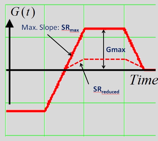
Recently, compact 3T (C3T) MR was introduced with high-performance gradients and smaller bore size3,4. A key feature of the C3T is its high performance gradients3,5,6 capable of 80mT/m amplitude and SRmax=700T/m/s simultaneously, with little or no peripheral nerve stimulation6,7. As some MR conditional devices are labelled for SRmax=200T/m/s, this seems to preclude scanning patients with them on the C3T. Here we investigate whether scanning patient with those devices could be feasible because the condition SRmax=200T/m/s is met at the location of the device due to the spatial fall-off of the gradient field, even while the brain is imaged at the full gradient slew rate performance of 700T/m/s. This premise is illustrated by Fig. 1, where a reduction in maximum gradient amplitude (due to gradient fall-off at the location of the device) produces a proportionate decrease in slew rate, because the ramp duration remains unchanged. Thus it may be possible for a patient with a spinal cord stimulator implanted in the lower back to undergo a head exam at full slew rate.
Methods
MR conditions for implanted devices were evaluated from package inserts, vendor websites (accessed 5 November 2018), and curated databases2. We recorded information about 21 implantable devices that satisfied the following criteria: 1) MR conditional, 2) labeled with a value for SRmax and 3) the device is typically implanted inferior to the patient’s clavicle, so that the effective slew rate on the C3T experienced at the location of the device is reduced compared to the imaging volume that includes the brain.
The spatial dependencies of the imaging gradient fields were generated for the physical X, Y, and Z gradient coils used in the C3T. The calculations used an electromagnetic (EM) simulation tool developed by GE Global Research, based on the specific gradient conductor layouts, Maxwell’s equations, and finite element analysis. The plots were normalized so that 10mT/m gradient amplitude was obtained at isocenter.
Results
The table shown in Fig. 2 lists MR Conditional devices meeting the criteria described in Methods. Note that this is representative sample, and is not intended to be comprehensive. It is also important to remember that before imaging anyone who has any of these implanted devices, it is critical to check the latest manufacturer’s guidance for any updates.
Figure 3 illustrates representative contour plots of the spatial dependence in the coronal plane for the amplitude of the three principal imaging gradient fields.
Discussion and Conclusion
If we are imaging the brain at SRmax=700T/m/s with the C3T, the slew rate condition of SRmax=200T/m/s requires that peak gradient amplitude be reduced from 10mT/m to approximately 2.8mT/m at the location of the device. As illustrated by the contours in Figure 3, that condition can be typically met, especially for spinal stimulators. For some devices, a coronal x-ray may be required to verify the patient’s device placement. Note that the field from the Z-gradient falls off the most slowly, so that axis may require de-rating with some devices. Finally, we note the plots show the three principal components of the gradient field used for imaging, e.g., Gx=dBz/dx, and other vector components may also be important.
These results indicate the C3T could potentially be used to obtain high-slew rate exams (SRmax=700T/m/s) from patients with implanted device labeled with the condition SRmax=200T/m/s. Of course, we always advocate following the manufacturer’s labeling for MR conditional, clinical exams. However we believe these results can be used to motivate IRB-supervised studies, and perhaps inform future changes to manufacturers’ implant labeling.
We note that other safe scanning conditions for the devices listed also include limits on the static magnetic field B0, and its spatial gradient, and SAR. To fully assess patient safety considerations, all the factors must be considered together. Here we focused on gradient slew rate. The main magnetic field and its spatial gradient of the C3T were previously reported8. We note that those results also show rapid spatial falloff, so do not suggest problems meeting the conditions for the devices listed here with the C3T. SAR effects on the C3T will be explored in a separate project.
Acknowledgements
This work was supported by research grant: NIH R01EB010065 and U01 EB024450.References
[1] Shellock FG, editor. Reference Manual for Magnetic Resonance Safety, Implants, and Devices: 2018 Edition: Biomedical Research Publishing Group, Playa del Rey California. ISBN 978-0-9891632-5-5.
[2] Magresource website; http://www.doctordoctor.biz/search/Login.aspx accessed 5 Nov 2018.
[3] Foo TKF, Laskaris E, Vermilyea M, Xu M, Thompson P, Conte G, Van Epps C, Immer C, Lee SK, Tan ET, Graziani D, Mathieu JB, Hardy CJ, Schenck JF, Fiveland E, Stautner W, Ricci J, Piel J, Park K, Hua Y, Bai Y, Kagan A, Stanley D, Weavers PT, Gray E, Shu Y, Frick MA, Campeau N, Trzasko J, Huston J, Bernstein MA. Lightweight, compact, and high performance 3T MR system for imaging the brain and extremities, Magn Reson Med 2018; 80, 2232-2245.
[4] Weavers PT, Shu Y, Tao S, Huston J 3rd, Lee SK, Graziani D, Mathieu JB, Trzasko JD, Foo TK, Bernstein MA. Compact three-tesla magnetic resonance imager with high-performance gradients passes ACR image quality and acoustic noise tests. Med Phys. 2016; 43:1259-64.
[5] Tan ET, Lee SK, Weavers PT, Graziani D, Piel JE, Shu Y, Huston J 3rd, Bernstein MA, Foo TK. High slew-rate head-only gradient for improving distortion in echo planar imaging: Preliminary experience. J Magn Reson Imaging 2016; 44:653-64.
[6] Lee SK, Mathieu JB, Graziani D, Piel J, Budesheim E, Fiveland E, Hardy CJ, Tan ET, Amm B, Foo TK, Bernstein MA, Huston J 3rd, Shu Y, Schenck JF. Peripheral nerve stimulation characteristics of an asymmetric head-only gradient coil compatible with a high-channel-count receiver array. Magn Reson Med. 2016; 76:1939-1950.
[7] In MH, Shu Y, Trzasko JD, Tao S, Gray EM, Huston J, and Bernstein MA. Reducing PNS with minimal performance penalties via simple pulse sequence modifications on a compact 3T scanner. International Society for Magnetic Resonance in Medicine, Paris, France, June 2018.
[8] Shu Y, et al. Static magnetic field (B0) gradient evaluation of a compact 3T MR scanner. ISMRM, Honolulu HI, April 2017.
Figures