4194
Comparison of Device Vibration Induced by Trapezoidal and Sinusoidal Gradient Waveforms1The xMR Labs, Physics and Astronomy, Western University, London, ON, Canada
Synopsis
Gradient induced vibration of a steel disk due to trapezoidal and sinusoidal gradient waveforms was measured at varying frequencies at 3 T. Results show displacement increased monotonically with decreasing frequency but peak acceleration, scaled to the peak gradient field, remained consistent for all experimental conditions. Sinusoidal dB/dt exposure as a function of frequency represents a practical conservative exposure condition for testing dB/dt-induced vibration in conductive devices during MRI.
Introduction
The potential for patient harm due to medical device vibration is primarily due to device malfunction when exposed to changing gradient fields [1]. ISO 10974 currently recommends the use of trapezoids at varying frequencies to analyze the safety of device vibration in a scanner; however, the detailed shape of the trapezoid waveforms to be used are not well defined in the standard. A simpler, more convenient method (where available) involves using sinusoidal waves at fixed frequencies instead of trapezoids. In this study an investigation is made as to whether sinusoid gradient waveforms can be used to conservatively characterize the extent of vibration as compared to trapezoidal waveform exposure.Methods
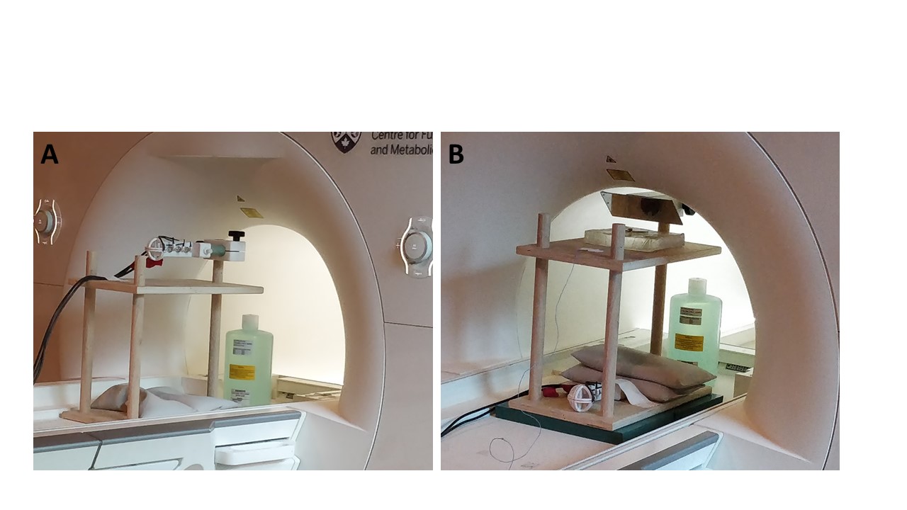
Experiments were performed at 3 T (Siemens Prisma-Fit) measuring the vibration of a standardized 50 mm diameter, 3 mm thick stainless steel disk. The disk was positioned parallel to the scanner bed on a 2.5 cm thick block of synthetic ballistic gelatin (10% gelatin, Clear Ballistics, Fort Smith, AR) in a location of the bore (X=0, Y=+24 cm, Z=+30 cm) verified to produce high dBy/dt values. Per the requirements of Clause 10 of 10974, an EPI pulse sequence was used to generate trapezoids with repetition frequencies of 300, 650, 900 and 1200 Hz with a minimum train of 12 pulses. Continuous sinusoidal gradient waveforms were also generated for the same frequencies. The gradient field change (dB/dt) at the disk location was measured using a 50-mm diameter, 3-axis dB/dt probe (10-loop induction coil on each axis).
Displacement (“vibration”) of the disk was measured with a Laser Doppler Vibrometer (OFV-505/5000, Polytec GmbH, Germany) with the laser reflected off a 45-degree mirror and focused perpendicular to the edge of a steel disk (Figure 1). A simultaneous measurement from an ICP accelerometer (352A21, PCB Piezotronics, Depew, NY) that was placed on the edge of the steel disk was used to measure acceleration. Both the peak displacement and acceleration were extracted and normalized to the peak dB/dt for each exposure condition.
Results
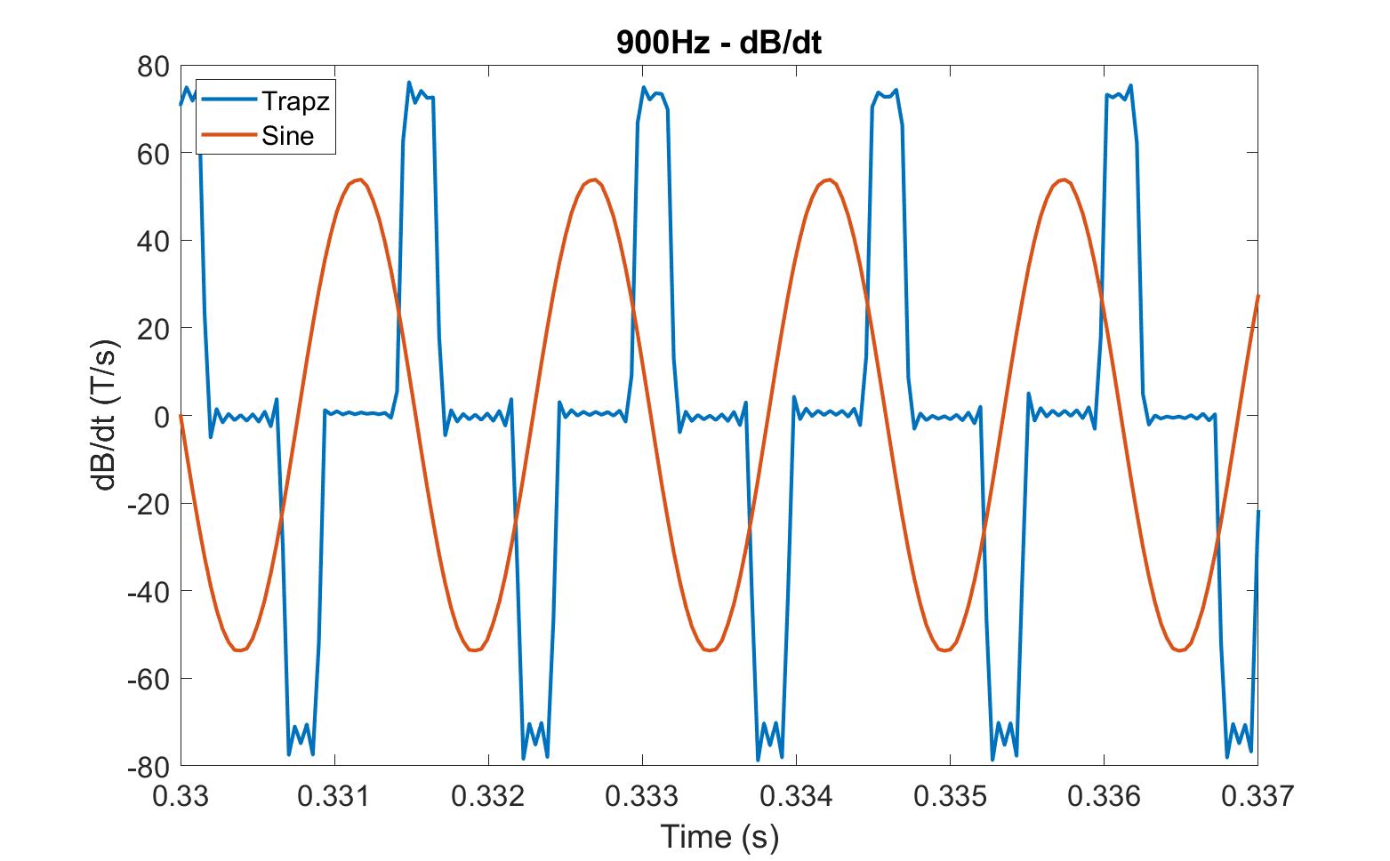
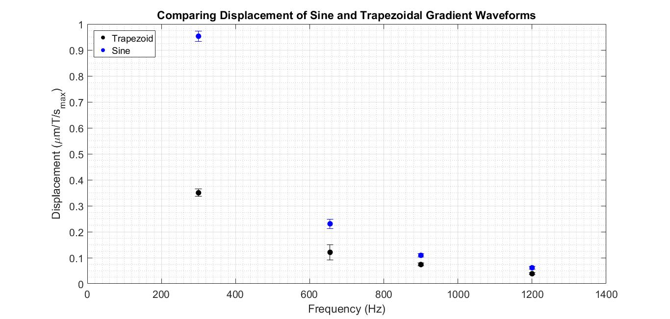
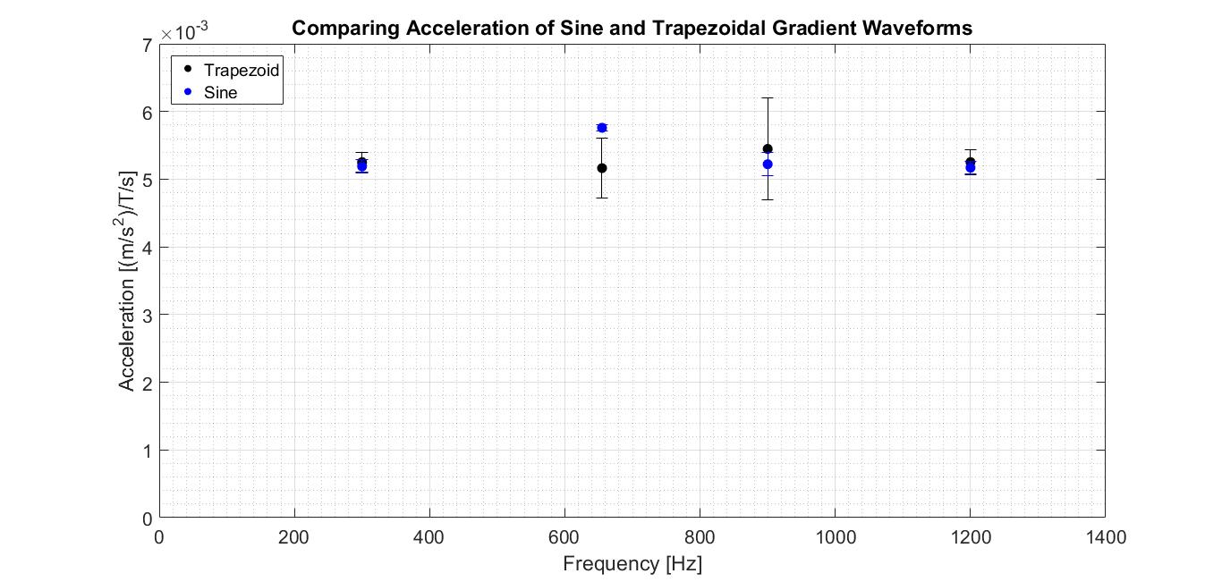
An example dB/dt waveform is shown in Figure 2, comparing sine and trapezoid waves at a single frequency. Displacement varied significantly with dB/dt waveform and as a function of frequency, and was consistently larger for sine waves than trapezoids (Figure 3). As expected, displacement increased monotonically with decreasing frequency. For acceleration results, it appears the peak disk acceleration when scaled to peak dB/dt remains within a consistent range of 5x10⁻³ to 6x10⁻³ (m/s2)/(T/s) regardless of the waveform shape or frequency (Figure 4).Discussion
The results are not surprising. Peak acceleration of the edge of the device is expected to depend only on the peak dB/dt, whereas peak displacement (which would be related to the acceleration via double integration over time) is a combination of the dB/dt waveform and time. The sinusoid and trapezoid waveforms have the same peak dB/dt (once normalized) and hence the accelerations are expected to be consistent. The displacements increase with decreasing frequency because of the time-integral.
These results do make clear a limitation of the testing as described in Clause 10 of [1], and that is that the trapezoid exposure waveform needs to be more completely defined. It is possible to obtain very different amounts of displacement even at a single exposure frequency, depending on the duty-cycle of the dB/dt waveform at that frequency. Sinusoids of course have a fixed “duty-cycle to frequency” relationship, and there is no ambiguity there. The worst-case displacement scenario would be expected to occur with a triangular gradient waveform (which would have a 100% dB/dt duty-cycle) with a high slew rate as the dB/dt integral would have a maximum area under the curve. However, an extended triangular gradient waveform is very rare in MRI. We believe that the sinusoidal waveform (which is also very rarely used in pure form) represents a practical “worst-case” waveform for dB/dt exposure. The sinusoid waveform is conservative in terms of the induced displacement as compared to typical trapezoidal waveforms as would normally be used. The sinusoid is also easy to define for the purposes of testing, since there is no requirement to separately define a dB/dt duty-cycle for a sinusoid.
Conclusion
Sinusoidal dB/dt exposure as a function of frequency represents a practical conservative exposure condition for testing dB/dt-induced vibration in conductive devices during MRI. A sinusoidal exposure reproduces the maximum accelerations as compared to a trapezoidal waveform, and results in conservative (i.e. higher) values of displacement. For these reasons, we believe that sinusoidal dB/dt exposure is a valid and conservative method for conducting vibration testing of devices per the requirements of ISO 10974.Acknowledgements
This work has been supported by NSERC and the Ontario Research Fund.References
[1] ISO/TS 10974. Assessment of the safety of magnetic resonance imaging for patients with an active implantable medical device; 2018Figures