4193
Verification and validation of a dB/dt exposure system using a robotic positioning system and induction field probe.1The xMR Labs, Physics and Astronomy, Western University, London, ON, Canada
Synopsis
In this abstract a semi-automated verification and validation protocol for a dB/dt system are presented. A dB/dt coil was simulated, fabricated, and mapped with both a hall probe and dB/dt probe using a positioning robot. All measured values, both DC and dB/dt, matched the expected values over the exposure volume. In addition, dB/dt measurements in air and in saline verify the consistency of the magnetic field in a typical device testing media.
Introduction
For ISO 17025-compliant testing procedures, a proper verification and validation (V&V) protocol for test platforms is required. The ISO 10974 [1] medical device testing standard requires devices to be exposed to a continuous dB/dt field of 42 T/s rms at 270 Hz for 30 minutes (ISO 10974, Section 9; “Gradient-induced device heating”) and various trapezoidal waveforms of up to 150 T/s peak with slew time as short as 0.1 ms (ISO 10974, Section 16; “Gradient-induced malfunction”). In this abstract the results of a semi-automated V&V protocol for a dB/dt system are presented.Methods
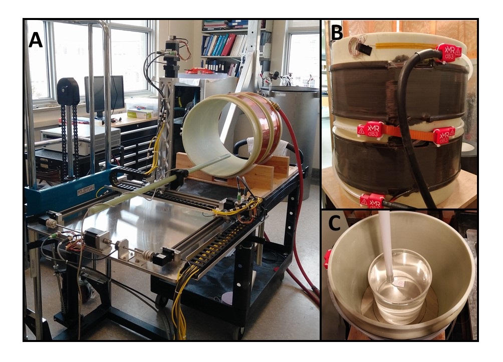
A large-bore split solenoid dB/dt coil was modeled using methods previously described by Martire et al. [2] and fabricated in our laboratories to be able to handle all ISO 10974 requirements for gradient (dB/dt) testing. The dimensions were set to have a coil inner winding radius of 24.8 cm and height of 34.1 cm to maximize the exposure region within the coil. The coil was a split design with 24 windings on layer 1 and 23 on layer 2, on each side of a 7.7 cm gap. The DC magnetic field produced by the system (when carrying DC current from a 50 A DC power supply (6032A, Agilent, California, USA)) was measured using a calibrated, NIST-traceable 3-axis Hall probe (F3A-03A05F-A50M25KM, Senis AG, Zug, Switzerland) using 1 cm increments to obtain a magnetic field map and the corresponding coil efficiency map.
At frequencies less than approximately 1 MHz, the magnetic field within an electromagnet is simply the DC field map modulated by the current waveform; however, to verify this and demonstrate the dB/dt values produced within the system, the dB/dt coil was connected to a gradient amplifier (PCI 2100) and a 270 Hz waveform was generated with a calculated dB/dt of 35 T/s peak. The dB/dt field was mapped with a single loop inductive sense coil, radius of 1 cm, fabricated on PCB followed by an instrumentation amplifier with two stages to provide differential amplification, followed by a difference amplifier stage to remove the common-mode voltage. The amplifier was designed to have a gain of 100 and overall probe antenna factor determined to be 30.83 (T/s)/ V. The probe was encased in a 3D printed holder and sealed with a silicone coating to allow for additional mapping inside saline. Field probe data was collected using an oscilloscope to determine the peak dB/dt at each location inside an empty 21 cm diameter phantom. Measurements were repeated with the phantom filled with saline (conductivity 0.47 S/m) to ensure the dB/dt magnetic field remains consistent within the test medium.
For all field mapping, a 3 axis in-house positioning robot was used to automatically move a probe (either Hall probe or dB/dt probe) in 1 cm increments throughout the volume of interest. The robot was equipped with three Nema 23 stepper motors and driven with a controller (DMC-4133, Galil, California, USA). A custom Labview control software was designed to automatically record the time domain signal for each corresponding location which was further analyzed in Matlab (2018b) for comparisons against simulations. Figure 1 shows the field mapping robot and gradient coil setup.
Results
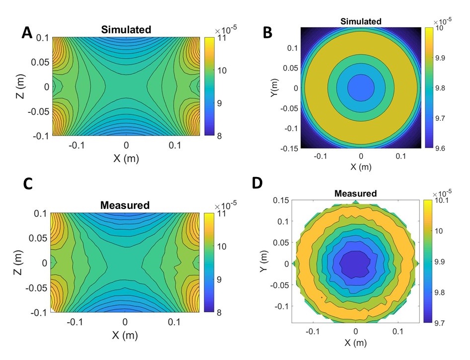
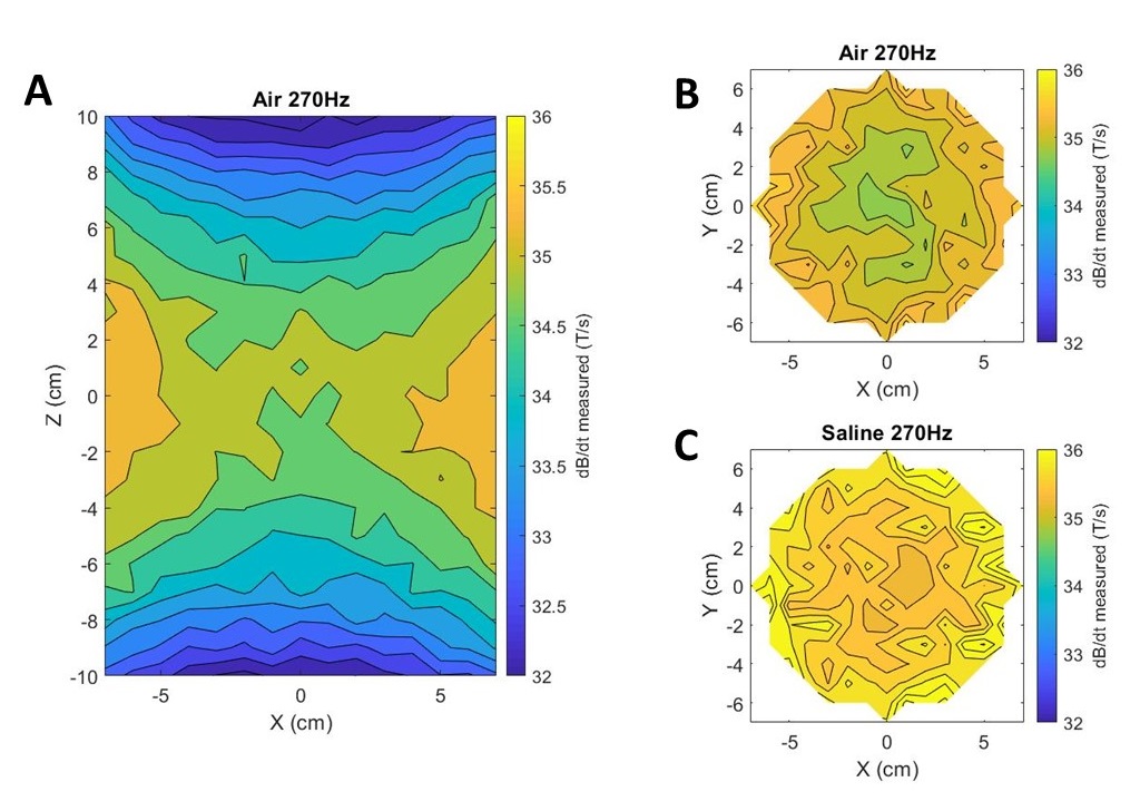
The simulated coil had an efficiency of 0.0973 mT/A with an estimated uncertainty on the order of 0.01%. The measured efficiency using a Hall probe matched at 0.097 ± 0.003 mT/A. Figure 2 shows the simulated and measured B-fields along the XZ and XY planes where all the location values matched to within 2%. Figure 3 shows the dB/dt measured field in air and saline. In air, the dB/dt in the isocenter was measured to be 34.7 T/s while in saline it was slightly higher at 35.3 T/s. All measurement in air and saline matched to within 2% of each other, and both were within 2% of the value calculated based on the DC field values.Discussion and Conclusion
The dB/dt test platform was successfully designed, constructed, verified and validated to have the expected, large volume of uniformity which is beneficial to allow for multiple simultaneous device tests and the opportunity to test relatively large and complex devices. All measured values, both DC and dB/dt, matched expected values to better than 2% over the exposure volume. The consistency of measurements for air and saline at 270 Hz verify the consistency of the magnetic field in a typical device testing media. The NIST-traceable data presented here supports the V&V process for the dB/dt exposure system, the robotic positioning system, and the dB/dt field probe used.Acknowledgements
This work has been supported by NSERC and the Ontario Research Fund.References
[1] ISO/TS 10974. Assessment of the safety of magnetic resonance imaging for patients with an active implantable medical device; 2018
[2] DJ Martire et al. Design of an MRI Gradient Field Exposure System for Medical Device Testing. ISMRM 2017. Abstract # 4334.
Figures