4192
On the RF Excitation of Overlapping Stents: Electro-optical E-field Measurements1Department of Radiology, Medical Physics, Medical Center University of Freiburg, Faculty of Medicine, University of Freiburg, Freiburg, Germany, 2Institute of Photonics and ICT (IPI), University of Applied Sciences HTW Chur, Chur, Switzerland
Synopsis
In stents, RF-induced heating is mainly associated with the antenna effect that occurs due to the thin and elongated geometry. Heating occurs mainly at the stent tip where a dipole-like E-field pattern is present. However, the E-field pattern and thus the locations of maximum heating change when two stents overlap. Using an optical setup for high-resolution E-field mapping, we provide further insight in the RF excitation of various combinations of stents in different geometric and dielectric configurations.
Introduction
In stents, RF-induced heating is mainly associated with the antenna effect that occurs due to the thin and elongated geometry. Thus, the energy deposited by a stent in the surrounding tissue is strongly dependent on the stent length compared to the RF wavelength1. Heating occurs mainly at the stent tip where a dipole-like E-field pattern is present2,3. However, the E-field pattern and thus the location of severe heating changes when two stents overlap which was recently assessed using simulations and temperature measuremens4.
In this study we provide further insight in the RF excitation of various combinations of stents in different geometric and dielectric configurations. Using an optical setup5, high-resolution E-field mapping is performed in the proximity of the stents to assess the dependency of the RF excitation pattern on the stent overlap.
Methods
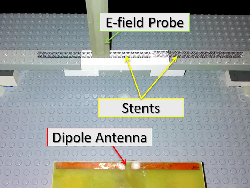
The E-field measurement setup is shown in figure 1. The two stents are positioned on a plastic holder with their long axis oriented parallel to a dipole antenna that was used for RF excitation. The antenna was tuned to 124 MHz (3T Larmor frequency). Line scans of the relative Ez component were acquired by moving the E-field probe along the long axis of the stents in steps of 0.5 mm. The distance between stent surface and the E-field probe was about 1.5 mm.
In this study, five combinations of two Nitinol stents (diameter: 5 mm) with different lengths were assessed: (i) 40/30 mm, (ii) 80/30 mm, (iii) 120/30 mm (iv) 120/80 mm and (v) 150/80 mm. For each combination the distance between the stents was successively reduced in steps of 5 mm from a +5 mm gap spacing to a -10 mm overlap configuration. To assess the influence of the surrounding dielectric media, measurements were acquired with coated and uncoated stents and distilled water and physiologic saline solution (0.9% NaCl). In addition, two-dimensional Ez maps were acquired for combination (iv) with 5 mm overlap.
Results
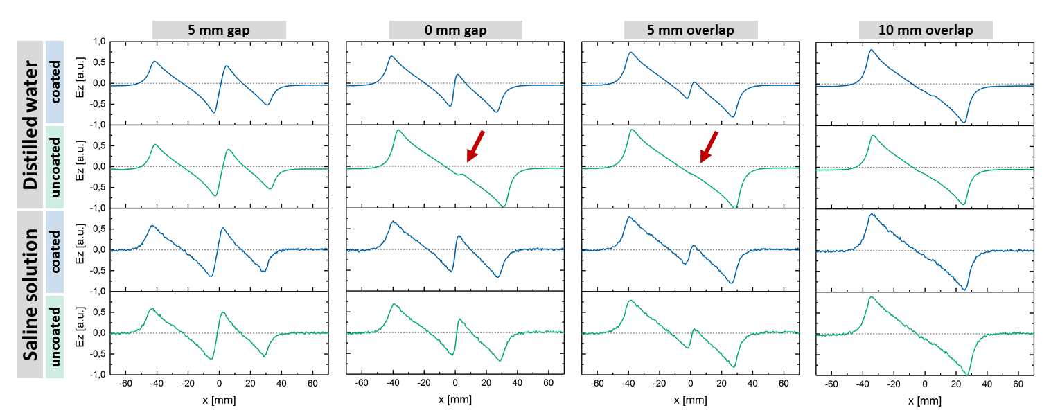
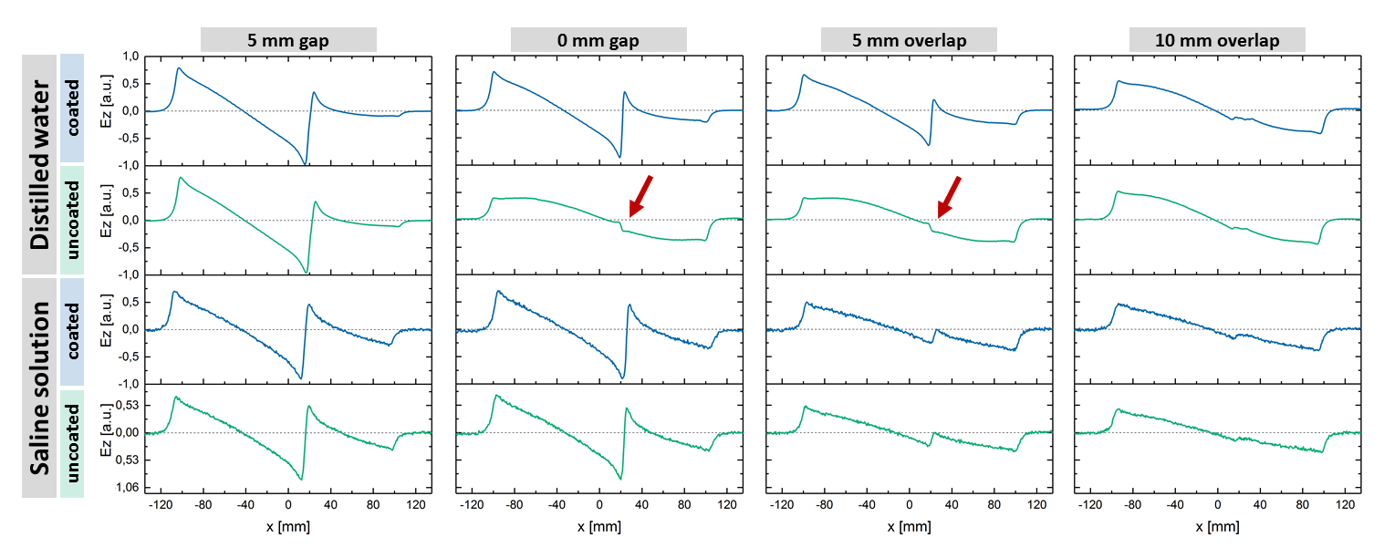
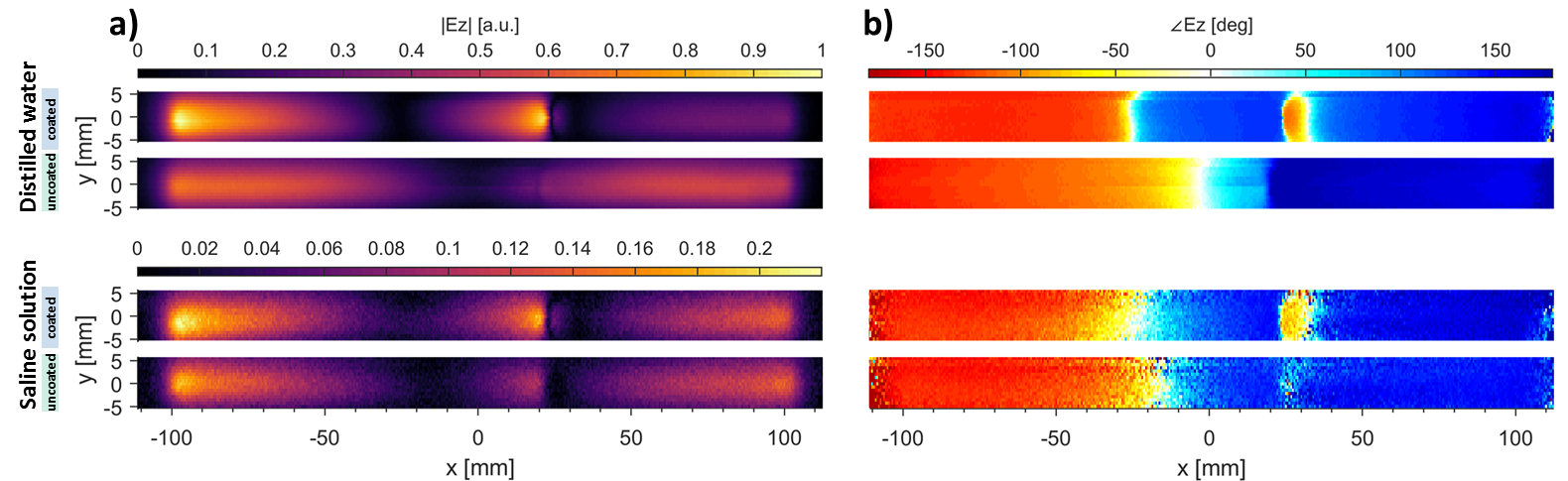
Figures 2 and 3 show the measured Ez for the stent combinations (i) and (iv). When the stents are separated, Ez is maximal at the stent tips and a dipole pattern is observed for both stents respectively. In contrast, overlapping stents with 10 mm intersection show a single dipole pattern over the entire configuration.
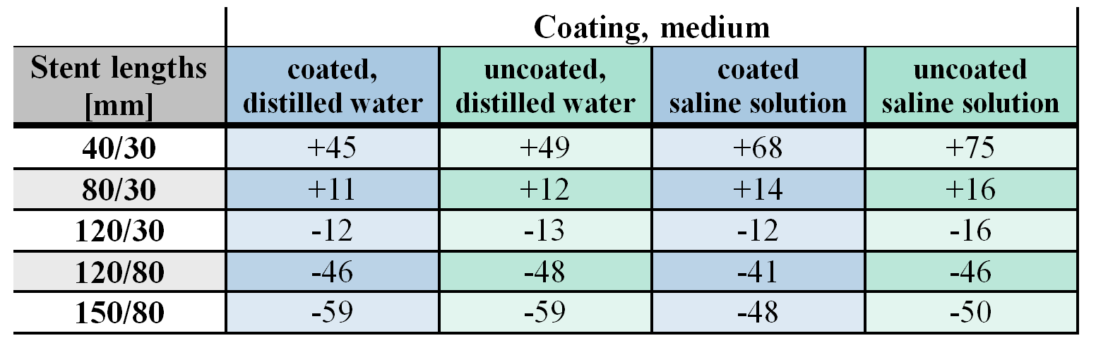
A comparison of the RF-heating potential between gap and overlap configuration is shown in table 1 by determining the ratio between the maxima of Ez of each plot respectively. In case (i) and (ii) the excitation increases significantly for overlapped compared to separated stents. In cases (iii) to (v) the overall length increases beyond the resonance length and the excitation decreases. For uncoated stents in distilled water a single dipole behavior is seen when the stents touch or have only a small overlap (red arrows in figures 2 and 3), whereas this is not observed with the same stents in saline solution. Here, the peak Ez is still seen at the point of contact of the stents and a 180° phase difference occurs at the point of contact. This behavior also seen in the 2D maps of Ez acquired for combination (iv) and an overlap of 5 mm (cf. fig. 4).
Discussion & Conclusion
Submillimeter near-field scans reveal that slight changes of the stent overlap has significant influence on the overall mode pattern and the local E-field excitation. Depending on the intersection length three different coupling states are observed: uncoupled, capacitively coupled and electrically connected. The response to excitation and thus, the heating potential is strongly dependent on the overall length of the two stent configurations relative to the resonance length but also on their coupling state, coating and the electrical properties of the surrounding media. Furthermore, strong gradients in Ez are observed between the two stents. This indicates, that also a strong tangential component of the E-field is present between the stents which corresponds to the findings of Serano et al4.
In summary, electro-optic E-field measurements provide reliable insights into the RF excitation properties of complex stent configurations such as overlap or tight spacings which are difficult to simulate and thus contribute to a better understanding of worst-case scenarios for RF safety assessments.
Acknowledgements
We gratefully acknowledge support from Stefan Polei and Cortronik, Rostock-Warnemuende, Germany as well as Claus Harder and BIOLAB Technology AG, Zuerich, SwitzerlandReferences
1. Song T, Xu Z, Iacono MI, et al. Retrospective analysis of RF heating measurements of passive medical implants. Magn. Reson. Med. 2018;80:2726–2730
2. Winter L, Oberacker W, Oezerdem C, et al. On the RF Heating of Coronary Stents at 7.0 Tesla MRI. Magn. Reson. Med. 2015; 74:999–1010
3. Santoro D, Winter L, Mueller A, et al. Detailing Radio Frequency Heating Induced by Coronary Stents: A 7.0 Tesla Magnetic Resonance Study. PLoS ONE 2012;7(11): e49963
4. Serano P, Iacono MI, Angelone LM, Rajan SS. RF Induced Heating of Overlapped Stents. Proc. Intl. Soc. Mag. Reson. Med. 24 (2016)
5. Reiss S, Bitzer B, Bock M. An optical setup for electric field measurements in MRI with high spatial resolution. Phys. Med. Biol. 2015;60(11):4355
Figures