4189
Compact 3T MRI for imaging patients with implanted devices: RF and SAR consideration1Radiology, Mayo Clinic, Rochester, MN, United States, 2GE Global Research, Niskayuna, NY, United States
Synopsis
Patients with certain implanted devices have been restricted from MRI exams with the whole-body transmit coil due to concern of local heating. A novel compact 3T (C3T) MRI scanner is equipped with an RF coil of larger radius but similar length as a T/R head coil. The purpose of this work is to assess the RF B1 field and E-field of the C3T T/R coil. RF heating risk of head imaging on C3T for patients with implanted devices was evaluated and compared with a commercial T/R head coil.
Introduction
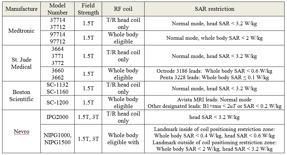
Patients with certain implanted devices have been restricted from MRI exams with the whole-body transmit coil due to the concern of local RF heating. Even if scanning is allowed, the MR conditions imposed by the device manufacturer may degrade the quality of the exam, or extend its duration. For example, a series of head-only models of spinal cord stimulator (SCS) (Table 1) only allows MRI scans with local transmit/receive (T/R) coil [1, 2]. Limiting scanning with the T/R coil precludes multi-channel receive coils, which not only produce higher SNR, but also are the prerequisites of advanced imaging applications like parallel imaging and simultaneous multi-slice imaging. Even for certain types of whole-body eligible SCS, a severe SAR restriction of as low as 0.1 W/kg is still imposed when the body transmit coil is used.
Recently, a novel compact 3T (C3T) MRI scanner has been developed for brain, musculoskeletal and infant imaging [3]. The scanner is lightweight, easy-to-site and has a high-performance gradient system (peak gradient strength of 80 mT/m and slew rate of 700 T/m/s). Compared to a conventional 3T MRI scanner with a transmit and receive radio-frequency (RF) body coil (diameter 60-72 cm, length 53-55 cm), the C3T scanner is equipped with a smaller RF coil (diameter 37.6 cm, length 40 cm). This RF coil is larger in diameter, but similar in length to the T/R split head coil (diameter 37 cm, length 41 cm). The rapid fall-off of magnetic and electric fields outside the RF coil of this C3T scanner could potentially enable and facilitate the scanning of patients with devices implanted inferior to the clavicle. The increased diameter enables use of the RF coil in conjunction with a multi-channel, receive-only head coils. The purpose of this work is to assess the changes in the RF B1 field and electric field (E-field) of the C3T T/R coil and evaluate the RF heating risks of head imaging on C3T for patient with implanted devices.
Methods
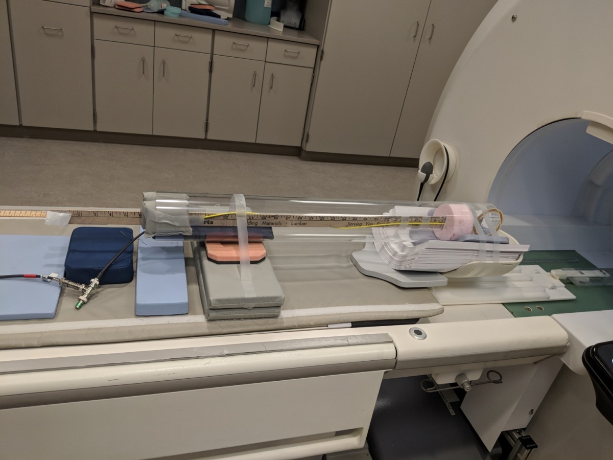
Relative changes in the RF B1 field along the isoline were measured [4, 5]. The RF pulse in a 2D gradient echo sequence (TR 150ms, TE 20ms, FA 90 degree) was run. A single-loop RF pick-up coil with a diameter of 7.5 cm, tuned to 128MHz, was used to detect the voltage induced by the RF B1 field. The pick-up coil was moved in the S/I direction along the isoline in increments of 1 cm, starting at isocenter and finishing at 60 cm inferiorly (Fig. 1). The peak-to-peak voltage amplitudes were recorded. A 25 ml bottle filled with water based solution of 0.05 g/l MnCl, 2.5 g/l NaCl was used to load the coil. At each position, measurements were repeated for two orthogonal pick up coil orientations (coronal and sagittal planes). The root-mean-square of the two orthogonal measurements were subsequently calculated and normalized to the measured value at isoenter.
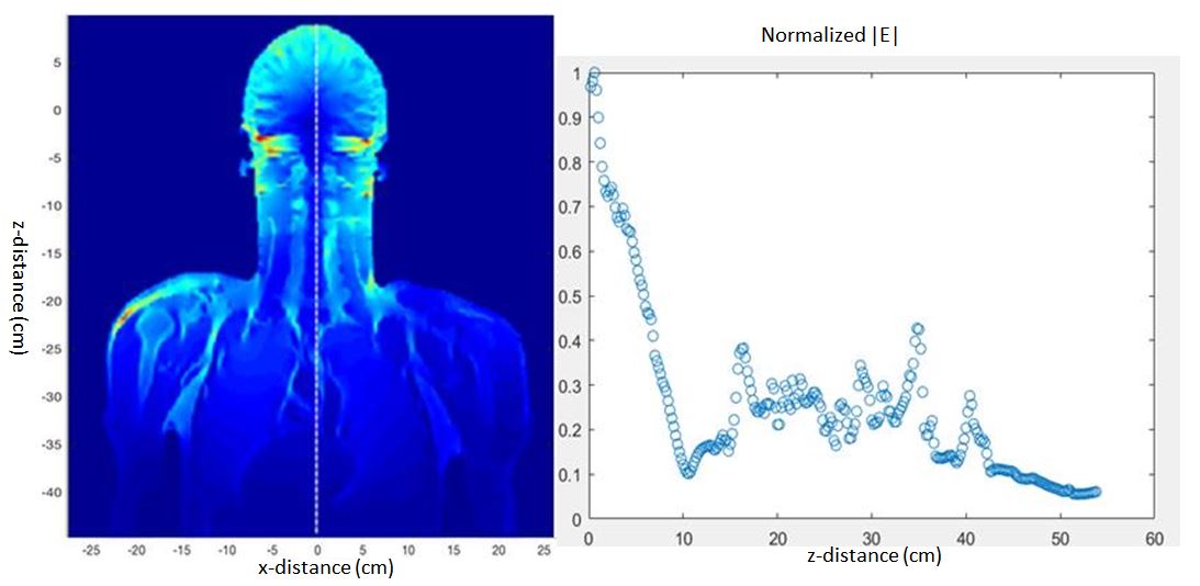
Numerical electromagnetic simulation was also performed, using Sim4life (ZMT Zurich MedTech, Switzerland) to calculate the E-field distribution. Specifically, the 16-rung high-pass birdcage head coil was driven in quadrature mode using the full Duke human body model [6]. The coil was excited by two edge sources (126.75 MHz, 1Vpp), and fields were extracted after -30dB simulation convergence. The field was calculated for B1+rms of 0.05 uT at an axial slice positioned on the glabella.
Results
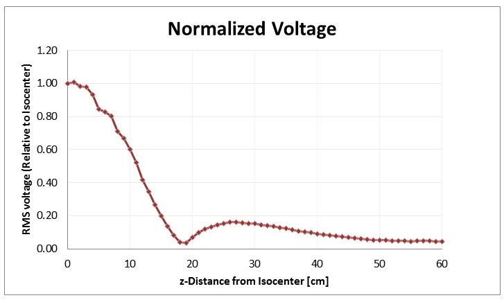
Normalized voltage measurement as a function of the distance along the isoline is plotted in Fig. 2. A coronal E-field map on the human model is shown in Fig. 3. The midline field magnitude is also plotted while normalized to isocenter value.Discussion and Conclusion
Both the RF B1-field measurement and the E-field simulation show that the RF power drops precipitously with increasing distance from the iso-center of the C3T scanner. The spatial dependence of the E-field simulation generally correlates well with the measured B1. Interestingly, the C3T power attenuation curve actually falls off more sharply than what was measured in a standard T/R head coil [4], which indicates using the C3T RF could still satisfy the manufacturer’s RF requirement for scanning the head-only SCS with a local T/R head coil.
These results could prove useful for evaluating the risk/benefit of using the C3T to scan patients with implanted devices like SCSs. We note that other MR conditions for safety include limits on the static magnetic field and its spatial gradient [7], as well as gradient magnitude and slew rate. To assess patient safety considerations, all MR conditions must be considered. Here we addressed RF and SAR; other factors will be explored in separate projects.
Acknowledgements
This work was supported by research grant: NIH R01EB010065 and U01 EB024450.References
[1] Mehul J. Desai, et al. The Rate of Magnetic Resonance Imaging in Patients with Spinal Cord Stimulation. Spine 2015 May 1; 40(9): E531–E537.
[2] Simopoulos TT1, Gill JS. Magnetic resonance imaging of the lumbar spine in a patient with a spinal cord stimulator. Pain Physician. 2013 May-Jun;16(3):E295-300.
[3] Foo TK, et al. Lightweight, Compact, and High Performance 3T MR System for Imaging the Brain and Extremities, Magn Reson Med. 2018 Nov;80(5):2232-2245.
[4] Favazza CP, et al. Evaluation of feasibility of 1.5 Tesla prostate MRI using body coil RF transmit in a patient with an implanted vagus nerve stimulator. Med Phys. 2017 Nov;44(11):5749-5754.
[5] International Electrotechnical Commission. IEC 60601-2-33, Ed. 2.0. Medical Electrical Equipment—Part 2-33: Particular Requirements for the Safety of Magnetic Resonance Equipment for Medical Diagnosis. Geneva, Switzerland: International Electrotechnical Commission, 2002.
[6] Christ A, et al. The Virtual Family--development of surface-based anatomical models of two adults and two children for dosimetric simulationsPhys Med Biol. 2010 Jan 21;55(2):N23-38.
[7] Shu Y, et al. Static magnetic field (B0) gradient evaluation of a compact 3T MR scanner. ISMRM, Honolulu HI, April 2017.
Figures