4188
Radiofrequency Heating of MR-conditional Needles during Interventional Magnetic Resonance Imaging at 1.5 and 3 Tesla Field Strengths1Department of Radiology, Musculoskeletal Imaging, New York University School of Medicine, New York, NY, United States, 2Johns Hopkins University School of Medicine, Baltimore, MD, United States, 3Russell H. Morgan Department of Radiology and Radiological Science, Johns Hopkins University School of Medicine, Baltimore, MD, United States
Synopsis
MR conditional 10, 15 and 20 cm cobalt chromium needles pose minimal risk of thermal injury when placed at a 45° to 90° angle relative to the patient table even after 5 minutes of continuous imaging with interventional pulse sequences (< 2.5 ˚C temperature rise). Higher temperature rises of up to 8˚C (3T) and 22˚C (1.5T) occur when needles are oriented parallel to the static magnetic field. If the needle must be placed in such orientation, low Specific Absorption Rate pulse sequences and needle lengths that differ substantially from half of the radiofrequency pulse wavelength should be used.
INTRODUCTION:
With increased clinical use of magnetic resonance imaging-(MRI)-guided interventional procedures, radiofrequency (RF) heating of metal instruments during such interventions have gained greater attention and is a potential safety concern. Heating of wire-shaped conductive devices has been shown to occur at the tip of devices and varies depending on wire length and its position in the magnet.1 Similarly, non-ferromagnetic metallic needles are expected to interact with the electromagnetic RF pulse. In this study, we aimed to quantify the heating of different MR-conditional needles during 1.5 and 3T imaging with pulse sequences that are commonly used during MRI-guided procedures.METHODS:
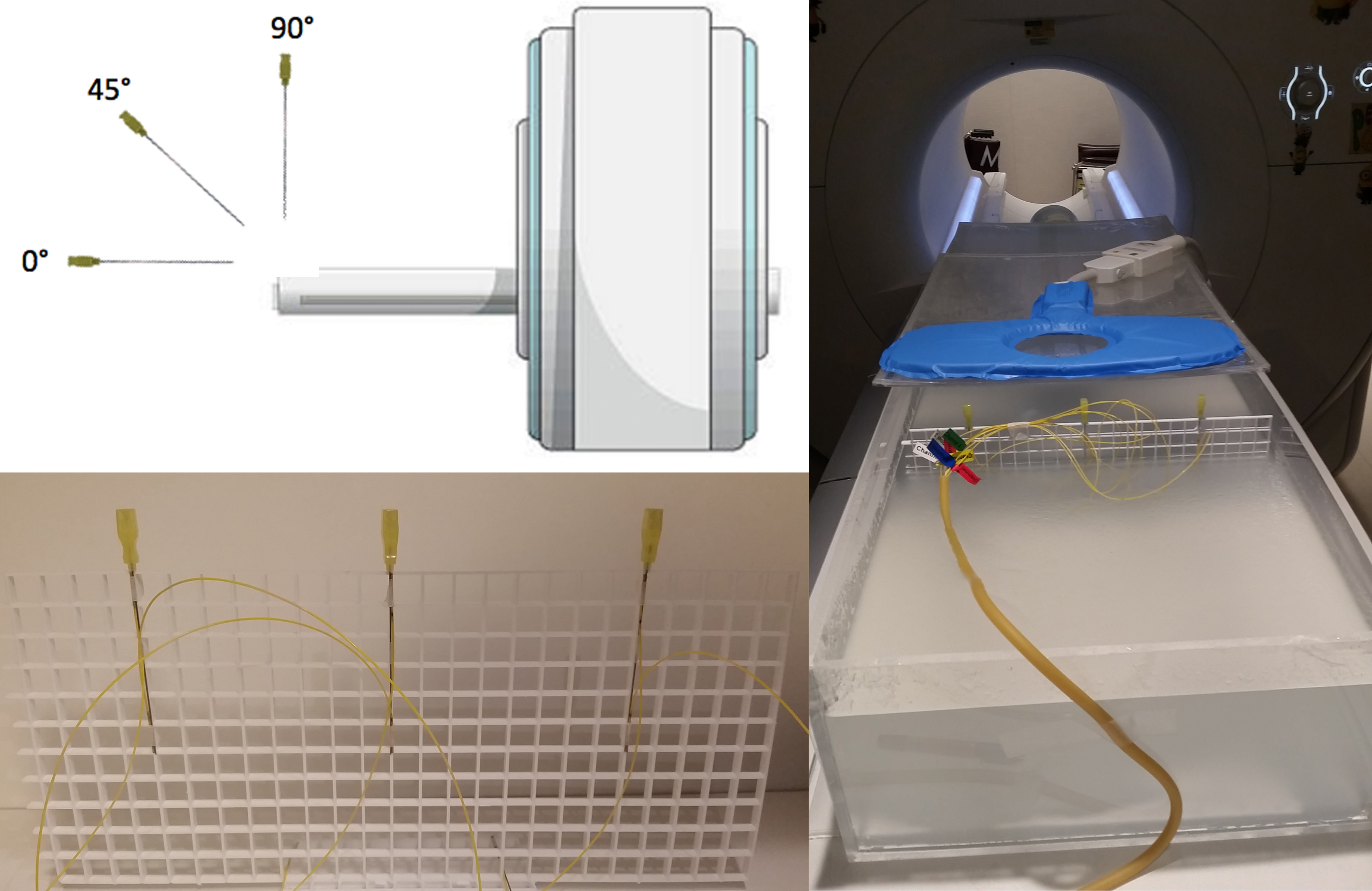
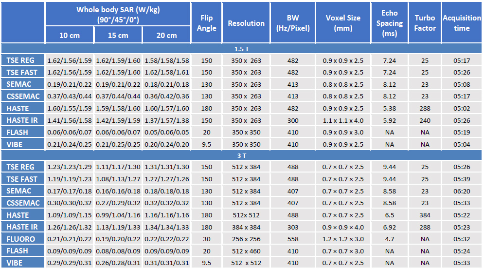
We used a standard ASTM gel phantom and clinical 1.5 (Magnetom Aera, Siemens Healthineers) and 3T (Magnetom Skyra, Siemens Healthineers) MRI systems.2 MR-conditional 20 gauge, 10, 15 and 20 cm cobalt-chromium Chiba Biopsy Needles (Cook Medical, Bloomington, IN, USA) were placed in three different orientations (90°, 45°, 0° with respect to the static field) at the center and equidistantly on each side to account for spatial variations of RF power deposition (Figure 1). Fiber optic sensors (Neoptix Inc., Québec, Canada) with 0.1 ˚C accuracy range and 1‐Hz sampling rate measured the temperature changes at the tip of each needle and 10 cm proximal to it along the needle. The interventional sequences tested (Table 1) included regular Turbo Spin Echo (REG TSE), accelerated TSE (TSE FAST), Slice Encoding for Metal Artifact Correction (SEMAC), Compressed Sensing (CS) SEMAC, Half-Fourier Acquisition Single-shot TSE (HASTE), HASTE Inversion Recovery (IR), fluoroscopic (FLUORO, 3T only), static (FLASH) Fast Low Angle SHot, and Volumetric Interpolated Breath-hold Examination (VIBE). All sequences had clinical acquisition times of < 1 min. However, in order to accentuate subtle temperature changes and emulate the effects of successive image acquisition during procedures, each sequence was acquired continuously for 5 min.RESULTS:
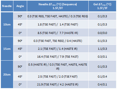
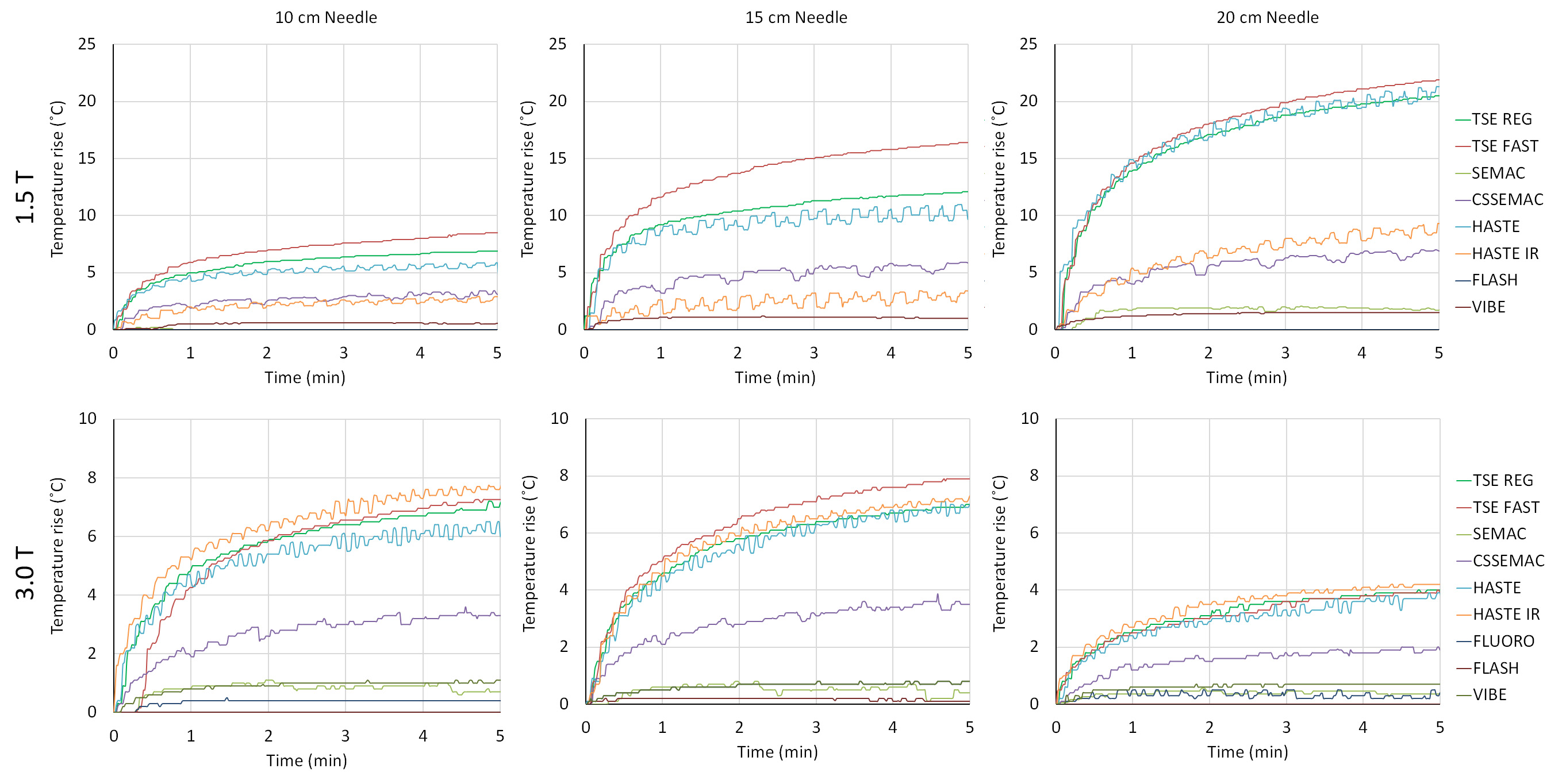
Outside the error margins, the heating at the tip of the needles was greater than the heating 10 cm proximal to the needle tip for all experiments. Our date showed spatial dependency of RF heating relative to the location of the needle tip in the axial plane, whereas needles on the bore’s left side heated the most. The maximum temperature rises for all needle lengths and orientations are summarized in Table 2. As seen, after 5 minutes of continuous imaging for orientations perpendicular and 45˚ oblique to the patient’s table, the needle temperature increases up to 2.5˚C; however, temperature increases of up to 8˚C (3T) and 22˚C (1.5T) occurred at the tip of the needles that were oriented in parallel to the table. Even 30 seconds of imaging with high Specific Absorption Rate (SAR) pulse sequences such as TSE and HASTE using a 20 cm needle parallel to the 1.5T magnetic field may result in temperature rises of more than 10˚C. At 1.5T, there is increased heating with longer needles (p<0.05 for all pair-wised comparisons). At 3T, 15, 10 and 20 cm long needles are respectively associated when the highest degree of heating (p<0.05 for all pair-wised comparisons). As expected, pulse sequences with higher whole body SAR result in higher of temperature rises. Accounting for slight difference in the pulse sequence parameters, for the tested needles, imaging at 1.5T field strength resulted in higher temperature rises compared to 3T.DISCUSSION AND CONCLUSION:
When placed at a 45° to 90° angle relative to the patient table, the tested MR-conditional needles pose minimal risk of thermal injury even after 5 minutes of continuous imaging (maximum temperature rise of 2.5°C). If the needed must be placed in parallel to the table and static magnetic field, three strategies may be implemented to minimize the risk of thermal injury: (1) use of shorter acquisition times by using pauses in-between acquisitions to allow needle tip to cool down. (2) avoidance of pulse sequences which deposit high energies into the patient such as TSE and HASTE. (3) use of needle lengths that are substantially different from half of the radiofrequency pulse wavelength (10 cm for 1.5T and 20 cm for 3T MRI).Acknowledgements
No acknowledgement found.References
1. Nitz WR, Oppelt A, Renz W, Manke C, et al. On the heating of linear conductive structures as guide wires and catheters in interventional MR. J Magn Reson Imaging. 2001;13(1):105-114.
2. American Society for Testing and Materials International. Standard test method for measurement of radio frequency induced heating on or near passive implants during magnetic resonance imaging: ASTM standard F2182-11a, 2002 (2011). West Conshohocken, PA: ASTM International, 2011.
Figures