4184
Safety Assessments in the Cascaded Media Using an Electro-optic Sensor-based Transfer Function Measurement Setup1Department of Radiology, Medical Physics, Medical Center ‐ University of Freiburg, Faculty of Medicine, University of Freiburg, Freiburg, Germany, 2German Cancer Consortium Partner Site Freiburg, German Cancer Research Center (DKFZ), Heidelberg, Germany, 3Institute of Photonics and ICT (IPI), University of Applied Sciences HTW Chur, Chur, Switzerland
Synopsis
MR safety evaluations of metallic implants/devices are performed in single homogeneous media. However, most of the implants/devices function in different media interfaces such as DBS and iEEG electrodes, catheters, biopsy needles…, etc. Loading of the conducting lines change drastically inside media with different dielectric properties, so does the RF-induced heating characteristics. To improve in vitro MR safety evaluations, we introduce a new TF measurement setup that allows safety evaluations in cascaded media (CM). The performance of the CM-TF setup was verified on isolated and bare lead wires immersed in air/tissue-simulating-medium interface by comparing to FDTD simulations and analytical models.
Introduction
RF-induced heating around conducting wires is a result of the coupling of electric (E) field distributions with the wire (1,2). MR safety of metallic wires is evaluated by temperature measurements (3), by simulations, or transfer function (TF) measurements, or a combination of these (4,5). The ASTM standards requires that MR safety measurements wire-type implants or instruments are performed in homogeneous media; however, most DBS and iEEG electrodes, catheters or biopsy needles operate in different media. Electrical loading of the conducting lines changes drastically when media with different dielectric properties are present, and so does the RF-induced heating.
Heating can be controlled by changing the termination impedance (6,7), for which an in vitro safety assessment within cascaded media (CM) is needed. TF evaluation in cascaded media has so far only been performed using FDTD simulations (8). Here, we introduce a new TF measurement setup with CM. Fully immersed and CM-TFs of isolated and bare lead wires were measured in air/tissue-simulating-medium interface at various lengths using an electro-optical electric (E) field sensor (EOS). Results of the CM-TF setup were compared to FDTD simulations and SAR behavior was investigated using analytical modeling (6).
Methods
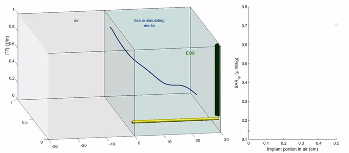
A CM-TF measurement setup was constructed with different local E field sources (i.e., excitor) for each medium and an EOS above the tip of the implant/device (Fig. 1). EOS is based on the Pockel’s effect, and the signal is transmitted by non-conducting fiber-optical cables, which are not causing electromagnetic interference (9,10). Local excitors are isolated loop resonators tuned with a capacitor (f0=124MHz), which are inductively coupled to a balanced current probe.
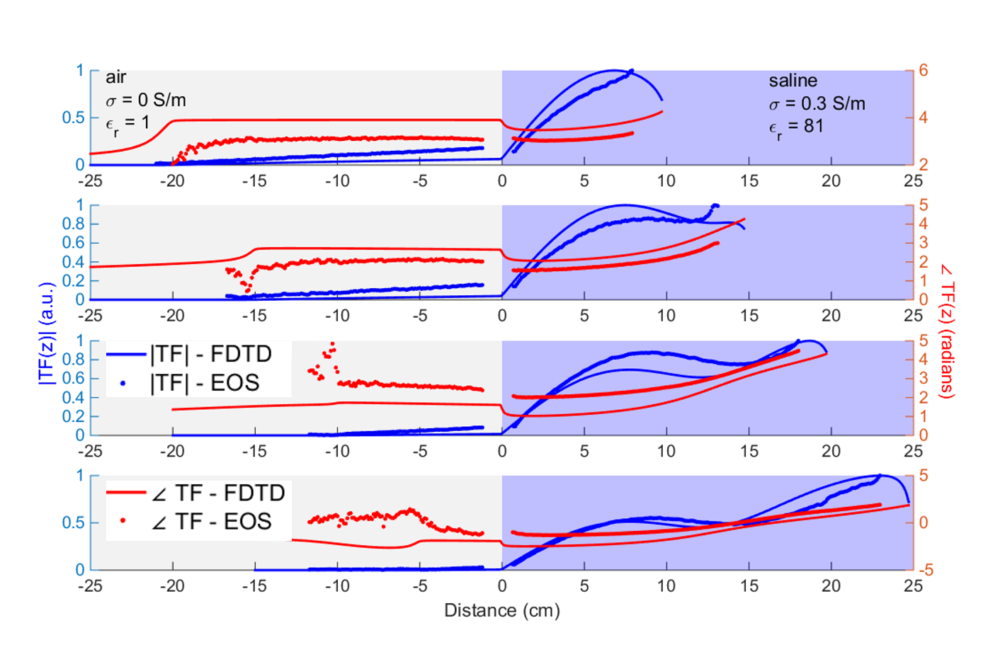
As bare and insulated samples, 30cm-long AWG16 wires were prepared where 1 cm of insulation was removed at the tips of the insulated sample. A PMMA container was used to separate two media: air (σ1=0S/m, εr1=1) and 1.55g/l NaClaq (σ2=0.3S/m, εr2=81). CM-TF measurements for air/NaClaq ratio of 30/0, 20/10, 5/15, 10/20, 5/25, 0/30 were performed with a 1mm resolution along the wire.
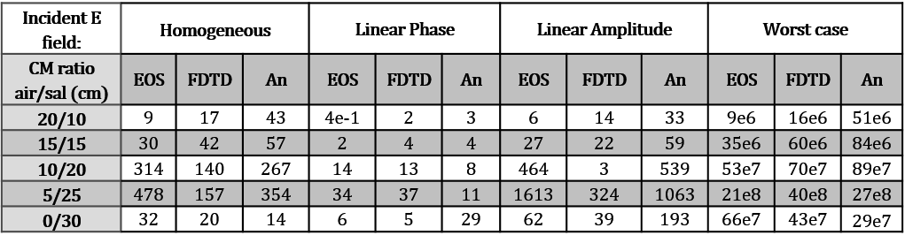
For comparison, FDTD simulations were done using Sim4Life (v4.1, ZurichMedTech AG), where TF was computed by a reciprocal approach with a monopole excitation source at the tip (10,11). Tip SAR computations under homogeneous excitation of $$$E_{tan}=1$$$ V/m for each case was also done for scaling of TFs. Tip SAR values for each CM-TF data set were also calculated for four incident field configurations with a peak E-field of 1 V/m: uniform, linear phase, linear amplitude and worst-case.
The analytical cascaded model was adapted from (6) and implemented in Matlab-R2017a (The MathWorks, MA). Here, finer step sizes of 1cm and 30mm were set for CM ratio and TF sampling steps, respectively.
Results
TFs from analytical
model, FDTD simulations and CM-TF setup measurements exhibit similar behaviors
including the oscillations and locations of abrupt phase changes for both bare
and uncapped wires (Figs. 2-5).
There is a
nonlinear relationship between the tip SAR and the CM ratio as shown by the analytical model results (Figs.3-4). Tip SAR in the fully immersed case is lower for both bare and the uncapped wires models.
Fig. 5 shows the estimated tip SAR values for all four incident field configurations. The CM ratio exhibiting the highest SAR varies for different incident field configurations. Tip SAR under uniform incident field show variations up to 98% according to the CM-TF measurements. Analytical model and EOS measurements overestimated the SAR by up to 50% compared to FDTD results for most of the cases (Fig. 5).
Discussion
Tip SAR for fully immersed wires does not represent the worst-case scenario of the CM-TF measurements, FDTD simulations and analytical modeling. Thus, the RF-induced heating cannot be predicted by single-medium assessment as is currently used as a standard. CM-TF, however, can be used to improve safety assessments.
Resonant wavelengths differ between simulation and measurement by 12.5% - these deviations can be attributed to uncertainties in the dielectric properties, because the conductivity was measured at low frequency. Also, the measurements setup has fairly narrow physical boundaries, whereas the FDTD simulation assumes boundaries at infinity (12) – thus, to increase precision, larger containers should be used for tissue-simulating media with low conductivity. A practical improvement to the CM-TF setup is replacing the resonant excitors by broadband micro-antennas, which deliver equivalent local E field independent of the medium. Nevertheless, the experiments showed that E fields around implants/devices can be measured in CM to assess more realistic safety ranges as in fully immersed measurements. In the future, temperature measurements will be performed to determine RF-induced heating.
Acknowledgements
No acknowledgement found.References
1. Shellock FG. Radiofrequency energy-induced heating during MR procedures: A review. J. Magn. Reson. Imaging 2000;12:30–36 doi: 10.1002/1522-2586(200007)12:1<30::AID-JMRI4>3.0.CO;2-S.
2. Yeung CJ, Susil RC, Atalar E. RF heating due to conductive wires during MRI depends on the phase distribution of the transmit field. Magn. Reson. Med. 2002;48:1096–1098 doi: 10.1002/mrm.10310.
3. American Society for Testing and Materials International. Designation: ASTM F2182-11a, standard test method for measurement of radio frequency induced heating near passive implants during magnetic resonance imaging. West Conshohocken, PA; 2011.
4. Technical Committee ISO/TC 150. ISO/TS 10974 Assessment of the safety of magnetic resonance imaging for patients with an active implantable medical device. ed. 1, clause 10.; 2012.
5. Park SM, Kamondetdacha R, Nyenhuis J a. Calculation of MRI-induced heating of an implanted medical lead wire with an electric field transfer function. J. Magn. Reson. Imaging 2007;26:1278–1285 doi: 10.1002/jmri.21159.
6. Özen AC, Lottner T, Bock M. Safety of active catheters in MRI: Termination impedance versus RF-induced heating. Magn. Reson. Med. 2018:1–12 doi: 10.1002/mrm.27481.
7. Silemek B, Açikel V, Yilmaz U, Atalar E. Wireless MR-Compatibility Control of Active Implantable Medical Devices. In: Proc. Intl. Soc. Mag. Reson. Med. 26. Paris, France; 2018. p. 644.
8. Min X, Sison S. Impact of Mixed Media on Transfer Functions with a Pacemaker System for Estimation of RF Heating During MRI Scans. In: ; 2017. doi: 10.22489/CinC.2017.272-135.
9. Reiss S, Bitzer A, Bock M. An optical setup for electric field measurements in MRI with high spatial resolution. Phys. Med. Biol. 2015;60:4355–4370 doi: 10.1088/0031-9155/60/11/4355.
10. Lottner T, Reiss S, Özen AC, Bock M, Bitzer A. Validating and Measuring Transfer Functions of Straight Wires using a Combination of an Electro-optic Field Sensor and Simulation. In: Proc. Intl. Soc. Mag. Reson. Med. 26. Paris, France; 2018. p. 642.
11. Tokaya JP, Raaijmakers AJE, Luijten PR, Bakker JF, van den Berg CAT. MRI-based transfer function determination for the assessment of implant safety. Magn. Reson. Med. 2017;78:2449–2459 doi: 10.1002/mrm.26613.
12. Zastrow E, Yao A, Kuster N. Practical considerations in experimental evaluations of RF-induced heating of leaded implants. In: 2017 32nd General Assembly and Scientific Symposium of the International Union of Radio Science (URSI GASS). IEEE; 2017. pp. 1–4. doi: 10.23919/URSIGASS.2017.8105350.
Figures