4181
Parallel RF Transmission for Safe 3 T MRI of Deep Brain Stimulation Devices: Effect of Mis-positioned Suppression Mode1Physical Sciences, Sunnybrook Research Institute, Toronto, ON, Canada, 2Medical Biophysics, University of Toronto, Toronto, ON, Canada
Synopsis
Magnetic resonance imaging (MRI) offers many benefits for deep brain stimulation (DBS) patients. However, radiofrequency (RF) heating remains a concern for MRI at 3T. Parallel transmission technology (pTx) has the potential to lower the risk by generating low electric-field regions at target locations. As pTx technology proceeds to imaging DBS patient, the impact of head motion becomes an important consideration. The present study investigates the impact of phantom mis-positioning when using pTx technology to suppress RF heating with results indicating head motion can potentially cause unsafe temperature elevations.
Introduction
Deep brain stimulation (DBS), where therapeutic electrical impulses are delivered through implanted leads to deep brain nuclei, is an effective treatment to improve quality of life for patients with neurological disorders (eg. Parkinson’s Disease). DBS treatments utilize MRI for precise electrode positioning and to evaluate post-operative effects. Functional MRI of DBS patients is also of research interest to study and help optimize the mechanism of effect. However, electrical charge can build up along the leads and causes localized radiofrequency (RF) heating effects, potentially damaging nearby tissue. Consequently, there is no regulatory approval for clinical MRI of DBS patients at 3 T and MRI safety remains an active topic of research in this context. A previous phantom study1 shows that parallel RF transmission (pTx) technology has the potential to produce a "suppression mode" that strongly attenuates electric-field strength to lower the risks of RF heating at specific target locations along DBS leads. Another study shows that the patient-specific lead trajectory is an important factor in the locations and amounts of RF heating2. As pTx technology proceeds to imaging DBS patients at 3 T, it is important to consider how the utility of suppression mode is affected if the zone of minimal electric field is mis-positioned away from the intended target. This could potentially occur due to inaccurate positioning of the head during patient setup, or due to head motion during imaging. The first of these two issues is examined here using 4-channel pTx MRI of a phantom at 3 T, using the suppression mode method developed by McElcheran et al.1.Methods
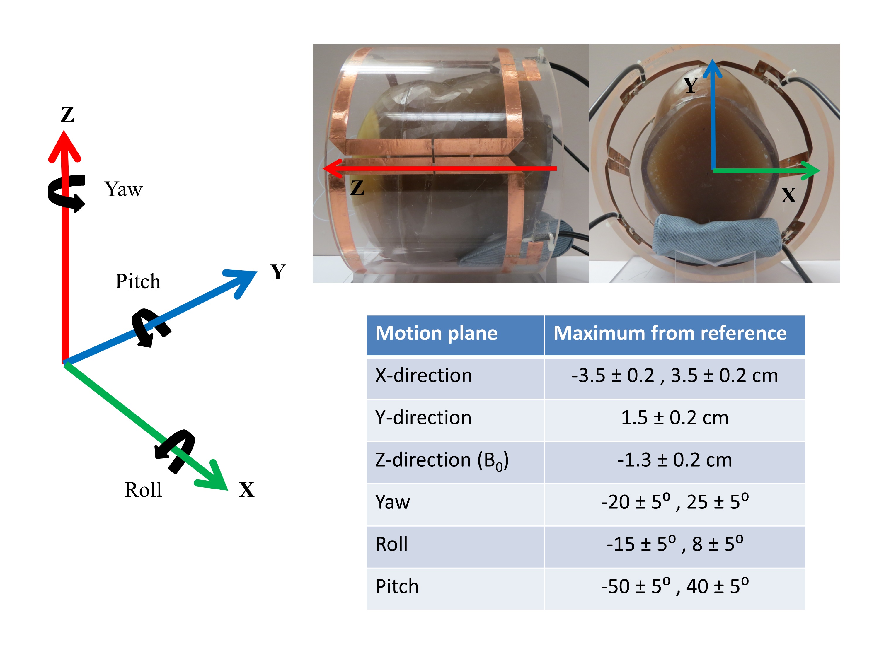
The effect of head displacement was studied using a custom 4-channel pTx system3 with 4 kW of peak output power, integrated on a research-dedicated 3 T MRI system (Siemens Magnetom Prisma). PTx suppression mode inputs to each channel were determined by previous FEKO (Altair Engineering Inc., Troy, USA) electromagnetic simulation results (amplitude/phase: ch1: -4.0dB/251⁰ ch2: -1.9dB/0⁰, ch3: 0dB/126.6⁰ and ch4: -1.3dB/112.2⁰) on a uniform head-shaped gel phantom with an insulated cooper wire implant3. First, MRI demonstrations of pTx technology were conducted (turbo spin echo scans, TR/TE/FA = 516ms / 6.7ms / 150⁰, 3m 45s scan time) in circular-polarized (CP) mode to induce RF heating, and in pTx suppression mode for reduced heating. This was followed by imaging in pTx suppression mode, where the head phantom was mis-positioned separately in all ‘six degrees of freedom’ (eg. x, y, z, yaw, pitch and roll directions), as depicted in Fig. 1 for the maximum displacement available in the pTx coil. Temperature measurements were recorded at the tip of the implanted wire using a fibre-optic temperature sensor (Opsens Inc., Quebec City, QC).Results
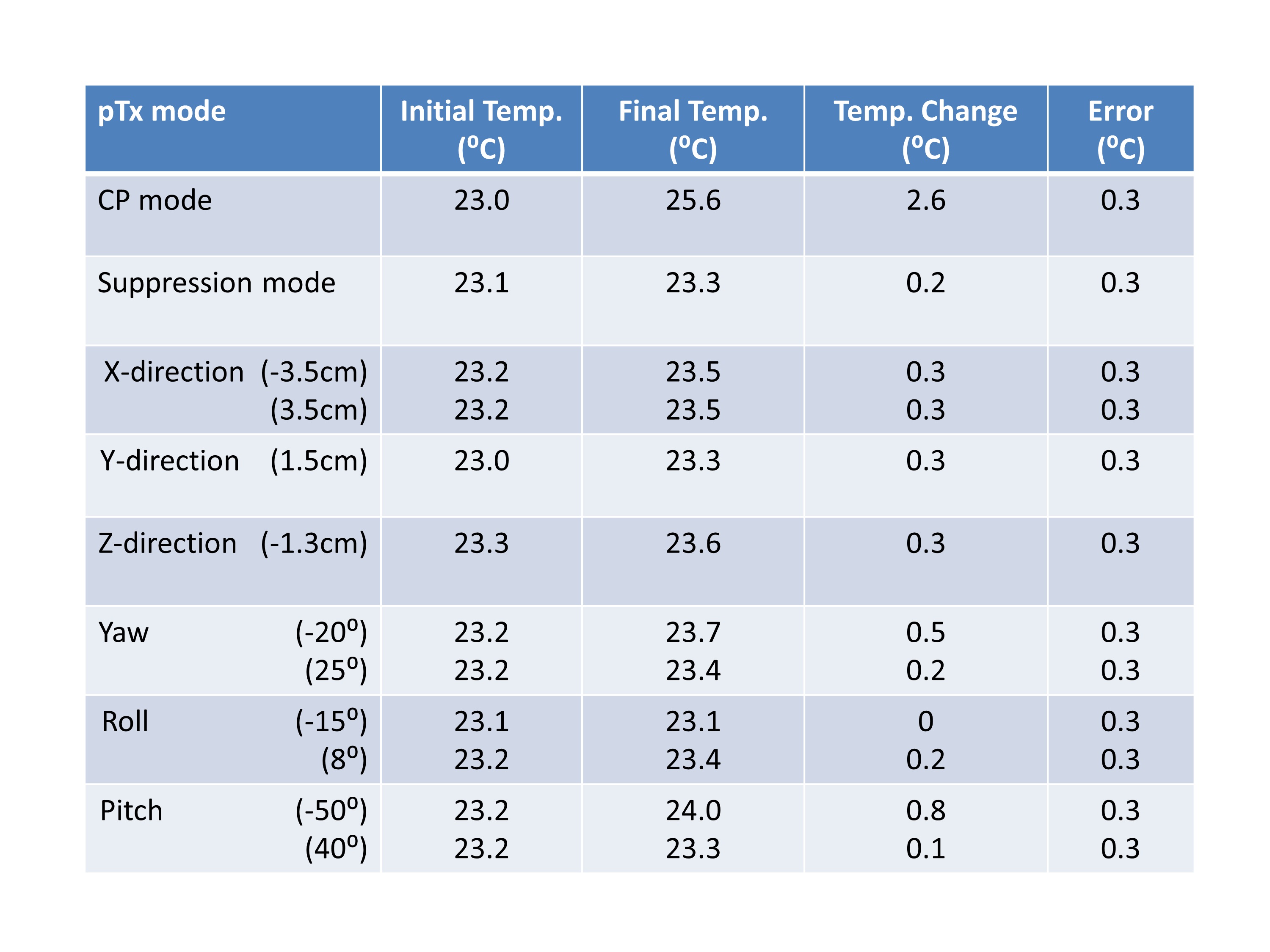
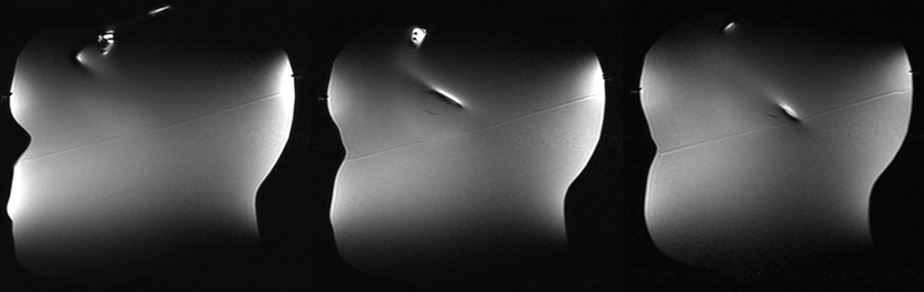
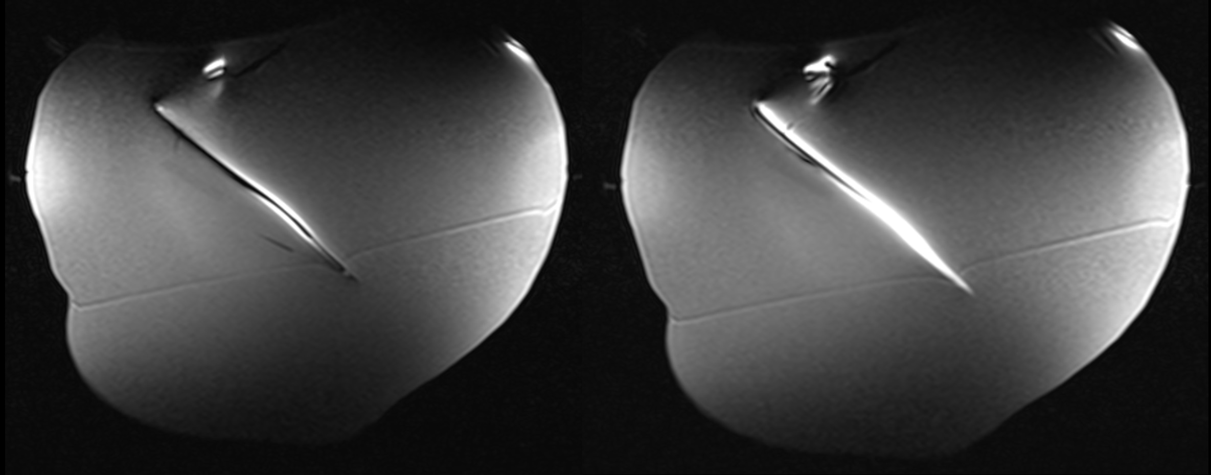
Fig. 2 summarizes the heating results that were obtained. RF heating in CP mode resulted in a temperature increase at the tip of the wire of 2.6 ± 0.3⁰C (from 23.0⁰C to 25.6⁰C), whereas suppression mode produced an increase of only 0.2 ± 0.3⁰C (from 23.1⁰C to 23.3⁰C). Head phantom mis-positioning (as per Fig. 1), recorded temperature changes ranging from 0 to 0.8 ± 0.3⁰C. Figs. 3 and 4 display MR images of the head phantom reconstructed in pTx suppression mode at the reference position and for a -50 ± 5⁰ pitch rotation that resulted in the highest temperature elevation, respectively. Despite that different cross-sections of the phantom are depicted in these two figures, it is evident that Fig. 4 shows substantially more RF coupling.Discussion and Conclusion
The pTx optimization method provides good suppression of RF heating at the desired target, with reasonable image uniformity. Promising robustness to mis-positioning was also demonstrated. A maximum temperature change of 0.8 ± 0.3⁰C was obtained for a large rotation in the pitch direction, and overall the displacements investigated were much larger than is likely to occur in clinical practice. However, strong RF coupling was observed in Fig. 4 along the wire, and it should be emphasized that temperature elevations in clinical practice are expected to be patient-specific, pulse sequence-specific and complex. Furthermore, it was observed that thermal equilibrium was not reached and temperature is likely to rise further with longer scan duration. The present study recorded temperature at a tip of the wire but other locations along its trajectory are susceptible to RF heating if the suppression mode is mis-positioned. Considering the FDA limit of 1.0⁰C heating for head MRI and the results presented in this study, head motion effects may pose imaging risks and further research will be required to investigate and establish safe pTx MRI protocols for DBS patients.Acknowledgements
No acknowledgement found.References
[1] McElcheran et al., “Parallel Radiofrequency Transmission at 3 Tesla to Improve Safety in Bilateral Implanted Wires in a Heterogeneous Model” MRM 2017
[2] Golestanirad et al., “RF-induced heating in tissue near bilateral DBS implants during MRI at 1.5 T and 3T: The role of surgical lead management” NeuroImage 2018
[3] Yang et al., “A Prototype Four-Channel Parallel Transmission System to Investigate MRI Safety at 3 T” ISMRM 2018
Figures