4177
Initial comparison of RF-induced heating in the ASTM phantom and a cadaver leg: a pilot study1The xMR Labs, Department of Physics & Astronomy, Western University, London, ON, Canada, 2Department of Medical Biophysics, Western University, London, ON, Canada, 3Fowler Kennedy Sports Medicine Clinic, Western University, London, ON, Canada, 4Lawson Health Research Institute, London, ON, Canada
Synopsis
The current standard for measurement of RF-induced heating for implanted devices is described in ASTM F2182-11a, however this method represents a highly conservative situation (i.e. higher than expected heating). Here we present a pilot cadaveric study investigating the relationship between heating of a standard device (10-cm Ti rod) placed within the ASTM phantom versus a cadaveric leg. At 64 MHz and 128 MHz, the respective implant heating in the cadaver was 1.57 and 9.87 °C, compared to 9.81 and 15.4 °C in the phantom. These results suggest a large margin between heating in the ASTM phantom and heating in-vivo.
Introduction
The current standard for measurement of RF-induced heating for implanted devices is described in ASTM International F2182-11a1. An implant under test is placed in a standardized rectangular phantom filled with gelled saline and exposed to RF fields for 15 minutes. The temperature rise over this period, scaled to calorimetry-determined whole-body SAR (WBSAR), is used for MR-conditional labeling of the device. In a separate measurement, peak device temperature rise for a standard 10-cm titanium rod after six minutes of RF exposure is used to calculate the Local SAR (LSAR) at the test location. The ASTM phantom is used because it represents a highly conservative situation (i.e. higher than expected heating) both in terms of the geometry and the material used. Results, and therefore labeling, obtained from tests using the ASTM phantom result in implants that exceed safety thresholds by a large margin. It is important to continue to investigate the nature and extent of the safety margin in these tests. Here we present a pilot cadaveric study at both 64 and 128 MHz, investigating the relationship between heating of a standard device (10-cm Ti-rod) placed within the ASTM phantom versus a cadaveric leg. We hypothesize that the heating will be significantly reduced in the cadaver as compared to the ASTM phantom.
Methods
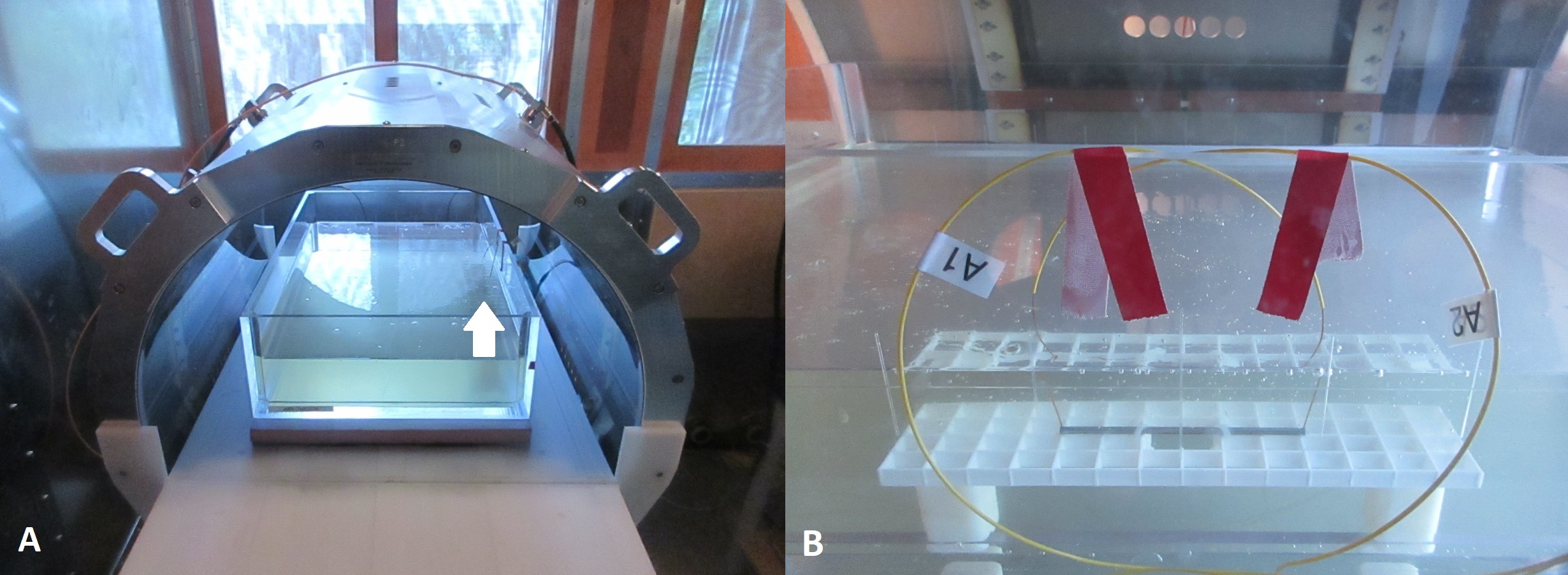
All RF-heating tests were performed on the Medical Implant Test Systems (MITS) 1.5 & 3.0, which are laboratory RF exposure platforms that operate at frequencies of 64 MHz & 128 MHz respectively2. The implant used was the 10 cm titanium rod described above. Temperature probes were placed centered in pre-drilled 1 mm holes, centered 1 mm from each end of the rod. In the phantom, the implant was tested in accordance to F2182-11a (Figure 1A).
The phantom was filled with HEC gel, to a depth of 9-cm. The implant was placed 3 cm from the side and at a depth of 30 mm (Figure 1B).
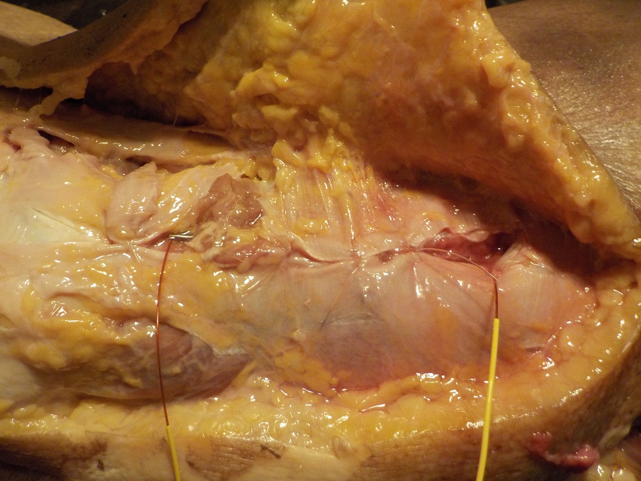
A fresh-from-frozen cadaver leg was obtained (Western University REB ID: 109545) and the implant was fixed to the anterolateral surface of the distal femur using zip-ties (Figure 2). The cadaver was positioned within the RF exposure systems so that the implant was in the same location (± 2 cm) and orientation as in the phantom. LSAR at 64 and 128 MHz was calculated by dividing peak device temperature after 6 minutes of RF exposure (ΔT360s) by 1.3 or 1.45, respectively1. Calorimetry measurements for the MITS 1.5 & 3.0 systems indicated WBSAR values of 2.94 (± 0.12) and 2.83 (± 0.15) W/kg, respectively. Calculated LSAR values were normalized to a WBSAR value of 2 W/kg via a linear interpolation.
Results
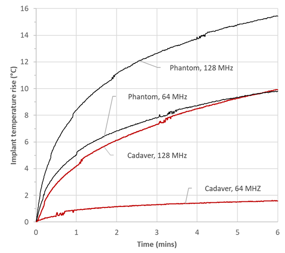
At 64 MHz and 128 MHz, implant heating in the cadaver (ΔT360s) was 1.57 and 9.87 °C, and normalized implant SAR was calculated as 0.82 and 4.81 W/Kg, respectively. In the phantom, implant ΔT360s was 9.81 and 15.4 °C, and normalized implant SAR was calculated as 5.13 and 7.51 W/kg at 64 and 128 MHz, respectively. Figures 3 shows implant heating in the cadaver and the phantom at both frequencies.Discussion and conclusion
As
expected, this pilot test demonstrated that in this example, implant heating was
significantly lower in the cadaveric specimen compared to the ASTM gel phantom
at both frequencies. Device heating
in the phantom was a factor of 6.25 and 1.56 higher (at 64 MHz &128 MHz,
respectively) compared to the cadaver, and this reduction is attributed to the differences
in geometry and electrical properties between the cadaver and the phantom. It
is possible the difference in heating reduction between frequencies could be due
to positioning errors within the systems. Poor visualization of the implant
within the cadaver may have resulted in higher SAR exposure (i.e. device was
closer to the hotspot), compared to the phantom (which provides easy visual
confirmation of implant positioning). Nonetheless, these results suggest that the margin
between heating in the ASTM phantom and heating in-vivo could easily be a
factor of 2-3 if not more. A
question that remains is: what features of an in-vitro phantom can be
introduced to control (i.e. limit) the margin between in-vitro and in-vivo results?
The cadaver is in a sense a perfect “geometrical representation” of the in-vivo
situation; however, it is completely non-functional. It is possible that a
simple geometry phantom, similar to the ASTM phantom, could be developed that
introduced an approximation of in-vivo function (e.g. perfusion). The question
would then be to determine the margins between device heating results as a
function of geometry and function, and this represents an important avenue for
future work in our program.Acknowledgements
The authors would like to acknowledge financial support from NSERC and the Ontario Research Fund.References
1. ASTM F2182-11a, Standard Test Method for Measurement of Radio Frequency Induced Heating On or Near Passive Implants During Magnetic Resonance Imaging, ASTM International, West Conshohocken, PA, 2011, www.astm.org
2. Medical Implant Test System, Zurich MedTech AG, Zurich, Switzerland.
Figures