4175
RF-induced heating in the vicinity of human depth intracranial EEG electrodes: effect of electrode and implantation simplification on computational EM simulations1Department of Clinical and Experimental Epilepsy, UCL Institute of Neurology, London, United Kingdom, 2Department of Clinical and Experimental Epilepsy, Epilepsy Society, Buckinghamshire, United Kingdom, 3Administration of Medical Physics, King Abdullah Medical City (KAMC), Makkah, Saudi Arabia, 4CIBM-AIT, Ecole Polytechnique Federale de Lausanne, Lausanne, Switzerland, 5Department of Biomedical Engineering, King's College London, London, United Kingdom, 6Developmental Imaging and Biophysics Section, UCL Great Ormond Street Institute of Child Health, London, United Kingdom, 7Wellcome EPSRC Centre for Medical Engineering, King's College London, London, United Kingdom
Synopsis
Empirical assessments on phantoms are essential to assess the health risks associated with performing EEG recordings concurrently with fMRI in humans; however they are time consuming limiting our capability to adequately investigate the range of scenarios encountered in real-world applications. Electromagnetic (EM) computational simulations can help to address this limitation, if they can be performed efficiently enough. Here we assessed the improvements of computational efficiency obtained by simplifying the representation of brain-indwelling EEG electrodes for EM simulations. The observed differences in estimated SAR between the full and simplified models can be understood in terms of a simple heuristic model.
Introduction
While RF-induced heating in the vicinity of invasive EEG electrodes and catheters has been characterised experimentally in test phantoms, these have typically covered a small number of electrode configurations, presumably due to the long experiment preparation times.1,2,3,4 Computational electromagnetic (EM) simulation has been proposed as an alternative route, by potentially allowing a much greater number of electrode implantation scenarios to be studied, with the aim of identifying the worst cases. However, realistic EM simulations can be very computationally demanding, depending on the level of anatomical and geometric detail included in the electrode models and number of electrodes.5,6,7 Here we studied the effect of simplifying the modelling of a depth intracranial EEG (icEEG) electrode on estimated SAR in the vicinity of electrodes and the computation times.Methods
Finite Difference Time Domain Method (FDTD) electromagnetic (EM) simulations were performed on a phantom8 using Sim4Life (version 3.2.2.1577; ZMT, Switzerland). Two models of a depth icEEG electrode were created: 1) Complete: 8 cylindrical contacts (perfect electrical conductor; diameter: 0.8mm, thickness: 0.15mm, length: 2.4mm), equally spaced (5mm) along the length of the electrode and each connected to a microwire running through the hollow electrode silicon tubing (following the design of an electrode model in common clinical use for the investigation of patients with severe epilepsy (SD08R-SP05X-000, Ad-tech, USA). 2) Simplified: a single electrode contact connected to a wire, obtained by the removal of the 7 most distal contacts, and their wire, of the Complete model. The length of the electrode, from the tip of the contacts end to connector end has the length of 380mm; it was connected to an 900mm-long extension cable. The electrode and extension were aligned along the coil’s longitudinal (Z) axis, inside the head part of the phantom. Different insertion depths and placements on or away from Z were simulated.
A low-pass head birdcage coil was used for RF excitation with specifications: diameter: 13.5cm, length: 27cm, 16 rungs, each rung (width: 1cm) has a capacitor (6.65pF). The phantom was placed inside the coil centred on the Z-axis and a PEC bore shield (diameter= 30cm) was placed outside the head coil.
EM simulations were performed as follows on a Windows PC (2.60GHz, 32GB RAM, two 8GB GPU): 15 periods, -40dB convergence level, 64MHz of harmonic excitation, head coil excited in circular-polarized mode, uniaxial perfectly matched layers for the global absorbing boundary conditions. The total grid size was 183MCells and 16MCells for the Complete and Simplified models respectively. The simulations formed the three following experiments, each comparing the estimated SAR in the vicinity of the tip electrode contact for the Complete and Simplified models:
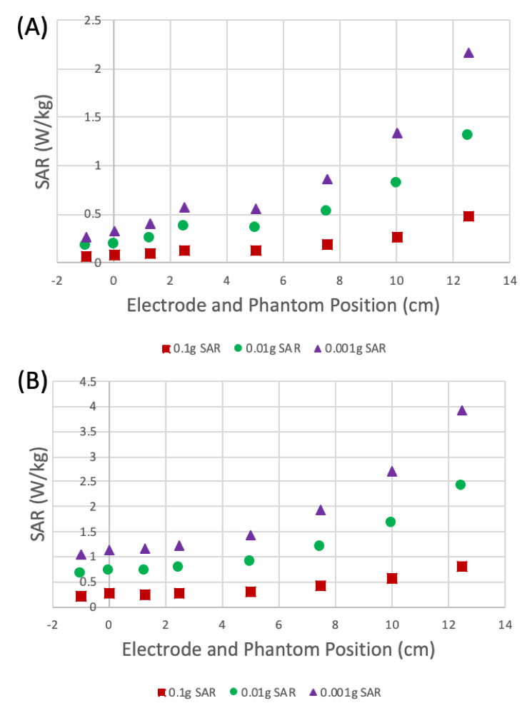
· Experiment 1: different phantom and electrode positions along Z (Figure 1(A)).
· Experiment 2: different electrode insertion depths (Figure 1(B)).
· Experiment 3: shortening of extension cable.
Local SAR averaged over 0.1g, 0.01g and 0.001g were calculated following IEEE/IEC62704-1.9
Results
The computation times ranged from 39h to 42h for Complete model, and 6h to 7.4h for the Simplified.
Experiment 1 (Figure 2): The patterns of local SAR values around the electrode tip contact as a function of the phantom+electrode position along Z for the Complete and Simplified models are similar, with the exception of a local maximum at Z = 2.5 for the former which corresponds to a plateau in the curves for the Simplified model. Furthermore, the SAR values for the Simplified model are double those for the Complete model.
Experiment 2 (Figure 3): Similarly to the results for Experiment 1, the SAR values as a function of electrode insertion depth for the Simplified model are double those for the Complete model. However, the SAR patterns for the two models differed with respect to the shape of the curve and the position of the maximum, reflecting the greater number of contacts in the Complete model.
Experiment 3 (Figure 4): the peak SAR is maximum for extension cable equal to 125cm.
Discussion and Conclusion
The observed patterns are consistent with a simple heuristic model of the effects of simplification in terms of magnitude and spatial configuration. In particular, we found that moving the electrode and the phantom together away from the head coil results in nearly identical patterns, with a constant amplification. For varying electrode insertion depths, the patterns differed in a way that matches the difference in number of modelled electrode contacts. We noted that the effect of extension cable length is in agreement with previous experiment that was performed on a conducting wire.5 These effects must now be verified empirically on a real phantom.Acknowledgements
This research was partly supported by National Institute for Health Research UCL Hospitals Biomedical Research Centre, United Kingdom.References
1. Carmichael DW, Thornton JS, Rodionov R, et al. Safety of localizing epilepsy monitoring intracranial electroencephalograph electrodes using MRI: radiofrequency-induced heating. J Magn Reson Imaging. 2008;28:1233–44.
2. Carmichael DW, Thornton JS, Rodionov R, et al. Feasibility of simultaneous intracranial EEG-fMRI in humans: A safety study. Neiroimage. 2010;49(1):379-390.
3. Boucousis SM, Beers CA, Cunningham CJ, et al. Feasibility of an intracranial EEG–fMRI protocol at 3 T: Risk assessment and image quality. Neuroimage. 2012;63(3):1237-1248.
4. Ciumas C, Schaefers G, Bouvard S, et al. A phantom and animal study of temperature changes during fMRI with intracerebral depth electrodes. Epilepsy Res. 2013;108(1):57–65.
5. Yeung CJ, Karmarkar P, McVeigh ER. Minimizing RF heating of conducting wires in MRI. Magn Reson Med. 2007;58(5):1028–1034.
6. Carmichael DW, Li Y, McEvoy A, et al. Estimating Specific Absorption Rate (SAR) during MRI in the human brain with intracranial EEG electrodes used for epilepsy monitoring: A preliminary study using finite integral technique (FIT) modelling. Proc. Intl. Soc. Mag. Reson. Med. 2008;16.
7. Ipek O, Hawsawi HB, Jorge J, et al. Safety of intracranial EEG recordings at 1.5 T MR: electromagnetic field simulation on a human body model. Proceedings of International Society for Magnetic Resonance in Medicine. 2017:2636.
8. ASTMF 2182-02a. Standard Test Method for Measurement of Radio Frequency Induced Heating near Passive Implants during Magnetic Resonance Imaging. ASTM Committee F04 on Medical and Surgical Materials and Devices, Subcommittee F04.15 on Material Test Methods. West Conshohocken, PA: ASTM International 2007.
9. IEEE/IEC62704-1 Recommended Practice for Determining the Peak Spatial-Average Specific Absorption Rate (SAR) in the Human Body from Wireless Communications Devices, 30 MHz-6 GHz: General Requirements for using the Finite Difference Time Domain (FDTD) Method for SAR Calculations, Draft, 2011.
Figures