4169
RF heating asymmetry in the implants placed at opposite lateral halves of the ASTM phantom1Case Western Reserve University, Cleveland, OH, United States, 2Cleveland Clinic, Cleveland, OH, United States
Synopsis
The rectangular shape of ASTM phantom may result into asymmetry in heating when an implant is placed symmetrically on the left and right lateral half of the phantom. In this work, we study the RF induced heating at the tip of a long insulated implant partially immersed into the crown of an ASTM phantom through two opposite lateral halves. The position of the wire on the left and right halves are symmetrical about the central sagittal plane. The results show that the RF heating of an implant is 2-3 times higher at left than at right half of phantom.
Introduction
RF heating studies for implants have been reported using the rectangular ASTM phantom, when a single implant is placed laterally offset from the center1,2. However, the electric field within the phantom is asymmetric due to the rectangular shape of the phantom and the polarization of the B1 RF field. This can lead to different levels of RF heating on two identical implants which are symmetrically placed about the sagittal plane, a situation relevant when considering RF heating issues for SEEG electrodes implanted in the brain. In this experimental measurements of asymmetric heating are compared with simulations, which indicate that the asymmetry in the heating is due to the asymmetry in the E-field.Methods
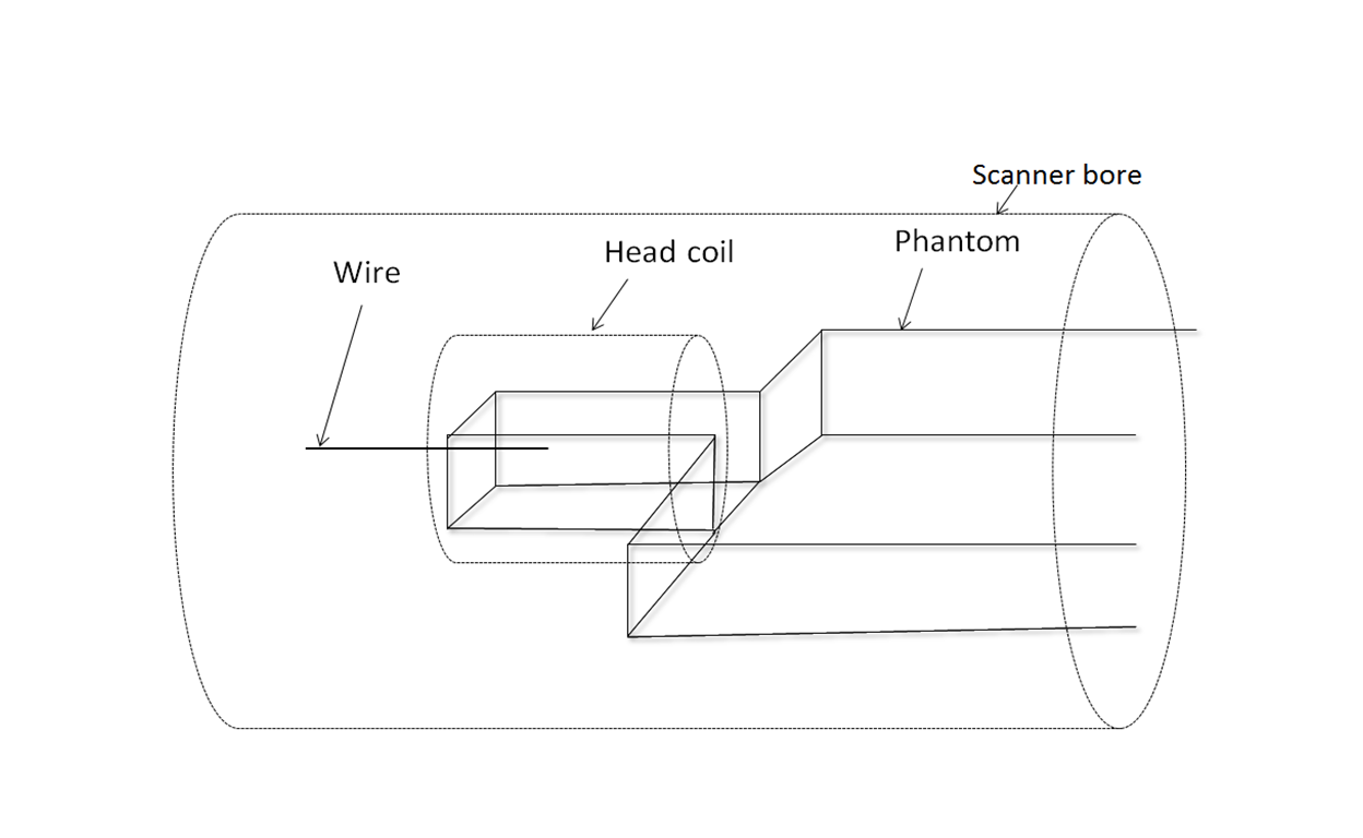
Experimental measurements of the temperature rise near the end of wire implants were performed on a Siemen’s Prisma 3 T MRI scanner using an ASTM torso phantom filled with saline water of conductivity 0.47 S/m and dielectric constant 80. Saline water was used to eliminate the possibility of inhomogeneity of phantom when using gel. A 0.7 mm diameter copper wire with insulation of thickness 0.45 mm was inserted into the crown of the phantom with 9 cm immersed length (Figure 1). At the end of the immersed end of the wire, 2 mm of insulation was removed leaving the copper exposed. The wire was inserted through the crown on the left lateral half of the phantom. A flouroptic temperature sensor probe placed at the tip of the wire was used to measure the temperature rise during a Turbo Spin Echo (TSE) sequence with head SAR of 2.8 W/kg and time averaged RF power of 8.9 W. Enough care was taken to position the thermal sensor close to the wire tip in both cases so as to minimize the errors in temperature measurements. A head Tx/Rx coil with circularly polarized B1 was used. The temperature rise was measured for a set of different length wires length ranging from 50 to 90 cm long. The measurements were repeated with the implant placed on the other side of the phantom at a mirror image location about the sagittal plane. Simulations were performed by applying finite difference time domain methods in XFdtd (XFdtd 7.4; Remcom Inc., State College, PA, USA) using RF power of 8.09 W.Results
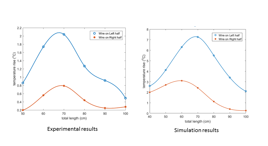
The experimental measurements and simulations of the temperature rise at the immersed tip of the wire is shown in Figure 2. In both the measurements and the simulations, the heating on the left wire is about 2-3 times the heating on the right wire when the wires are at the resonance length.Discussions
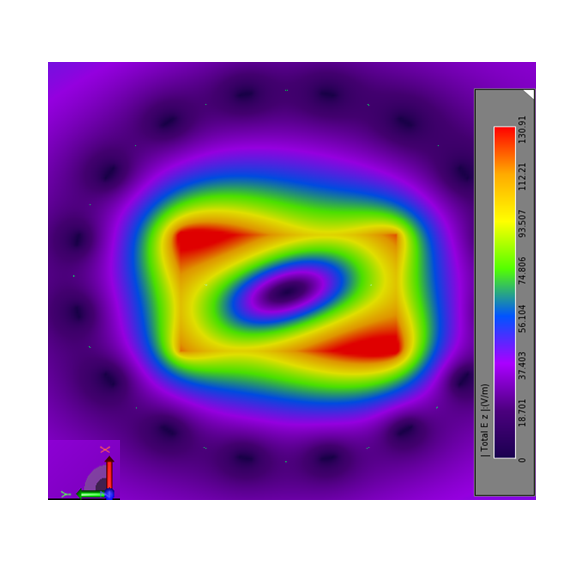
Figure 3 shows the distribution of E-field in the central transverse plane of the coil loaded with the phantom (without wire implant) for circularly polarized transverse B1 field. The results show that the heating of the identical implant at resonant length is different when it is introduced into the crown from left and right lateral halves respectively. The difference in heating on left and right could be understood from the plot of z-component of E-field as shown in the Figure 3. The rectangular shape of the phantom results in to the ellipsoidal distribution which results into the different E-fields at left and right half resulting into different heating. The magnitude of temperature rise in simulation is higher compared to that in experiment because the simulation does not take any convective heat transfer where as the saline water in the experiment is highly convective.Conclusions
In studies of RF heating with implants using the rectangular ASTM phantom, the left-right asymmetry of the electric field within the phantom, and the corresponding left-right asymmetry in the heating of implants is an important factor. Making measurements of RF heating on implants where the location of the implant is restricted to a single side may results in errors of a factor of 2-3 in the temperature rise. The measurements of temperature rise might underestimate the maximum heating of an implant if it is tested on the half showing lower heating compared to the position on the other half.Acknowledgements
This research was supported in part by fellowship from Cleveland Clinic Foundation Epilepsy centre.References
1. Liu Y, Chen J, Shellock F, et al. Computational and experimental studies of an orthopedic implant: MRI‐related heating at 1.5‐T/64‐MHz and 3‐T/128‐MHz. J. Magn. Reson. Imaging. 2013; 37: 491-497.
2. Bhusal B, Bhattacharyya B, Baig T, et al. Measurements and Simulations of RF heating of implanted Stereoelectroencephalography electrodes during MR scans. Magn. Reson. Med. 2018; 80: 1676-1685.
Figures