4168
Optimisation and validation of numerical simulation methods for parallel-transmit MRI near a hip implant at 7T1School of Information Technology and Electrical Engineering, The University of Queensland, Brisbane, Australia, 2Siemens Healthcare Pty Ltd, Brisbane, Australia, 3Centre for Advanced Imaging, The University of Queensland, Brisbane, Australia
Synopsis
Electromagnetic simulations are commonly used at 7T to predict and limit RF heating when pTx techniques are used. Correction of simulation results based on measured B1-maps and MR thermometry data have been shown to improve the simulation results, but may be affected by the presence of metal implants. In this work, B1-mapping and direct measurement of E-fields are used to validate simulation results of a pTx hip coil in the presence of a hip implant in a phantom. B1-data and/or E-field data were used and compared to correct simulation results.
Purpose
Parallel-transmit (pTx) systems show great promises to improve the radiofrequency (RF) homogeneity and control the specific absorption rate at ultra-high field MRI1-3. The risk of RF heating is commonly mitigated by using electromagnetic simulations to limit the input power, using SAR10g4. Recent studies have adapted this method to the case of metal implants, but require validations of simulations5,6. B1-mapping and MR thermometry are commonly used in validation frameworks7, but metal-induced artefacts require those methods to be modified8. In particular, the use of MR thermometry near large metal implants is currently limited. In this work, we introduce a validation framework using relative and absolute B1-mapping and E-field measurements, which allowed fast and reliable acquisitions with different shim settings. Calibration matrices were calculated to minimise the errors between measurements and simulations, using B1-data only, E-field data only, and in combination.Methods
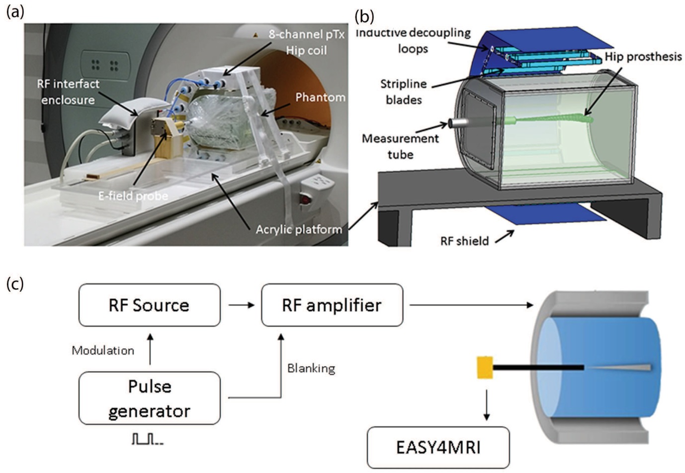
The E-field was measured inside the phantom along the z-axis of the tube shown in Figure 1a&1b, using an electric field probe (ER30V6, SPEAG). E-fields provided by individual channels were measured with a custom set-up shown in Figure1c, with 80W of input power and a 25% duty cycle. Additional validation was performed on a 7T whole-body research scanner (Siemens Healthcare, Erlangen, Germany), to allow measurement of the E-field when all eight channels were transmitting. Six different phase-only shims (POShims) were applied in a simple sequence consisting of 1 rectangular pulse: RF pulse length = 20 ms, TR = 50 ms, flip angle = 360°, duty cycle = 40 %, with an input power of 5.12 W per channel.
In addition, relative and absolute B1-maps were acquired with the following scan parameters: matrix size 168 x 168, in-plane resolution 1.5 x 1.5 mm2, slice thickness 1.5 mm, TE/TR 1.99/50 ms, flip angle 25˚, 2 averages, scan time 1 min 42 sec. The absolute B1-mapping sequence was repeated for the six phase-only shims previously introduced with the following scan parameters: matrix size 256 x 256, in-plane resolution 1 x 1 mm2, slice thickness 1.5 mm, TE/TR 1.82/10000 ms, flip angle 8˚, 3 averages, scan time 3 minutes.
The coil and phantom were modelled in Sim4Life, and the co-simulation method9 was used to optimise the values of the lumped elements to assist in obtaining S-parameters that matched the measured matching, tuning and decoupling. The resulting B1- and E-fields were exported to Matlab for correction based on measured data10,11. Fields from each channel were included in an optimization to reduce the difference between the measured and simulated E-fields (single and combined channels), and/or to reduce the root mean square error between measured and simulated B1-maps in an axial slice going through the tip of the implant. Results with no correction, correction based on B1 only, E-fields only, and both B1- and E-fields were compared.
Results
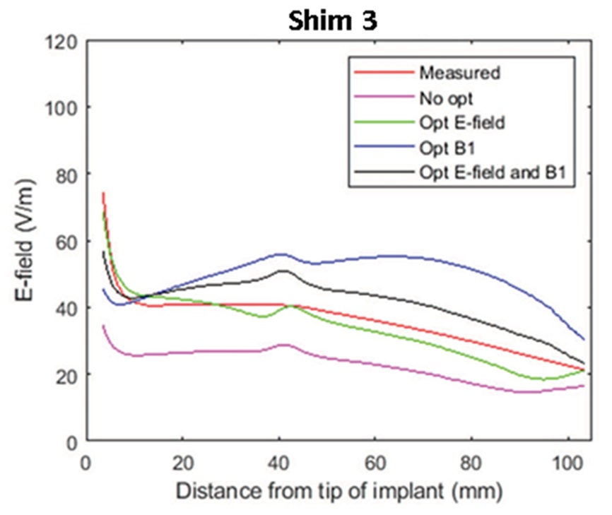
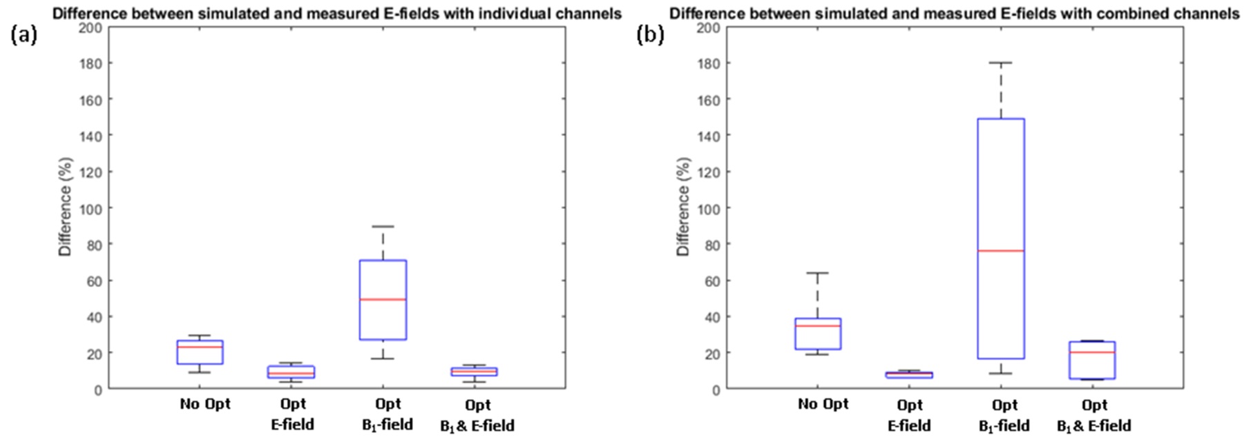
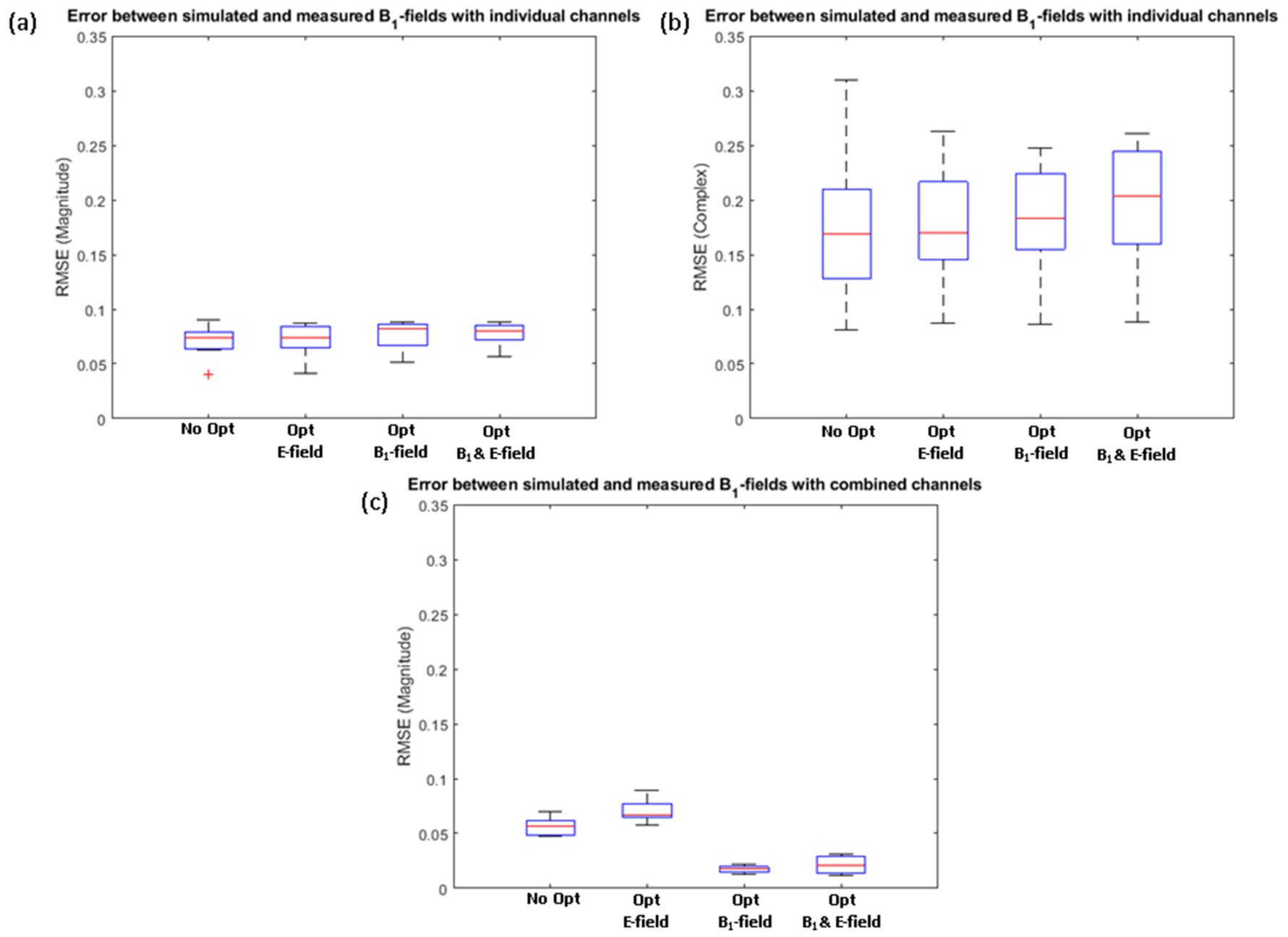
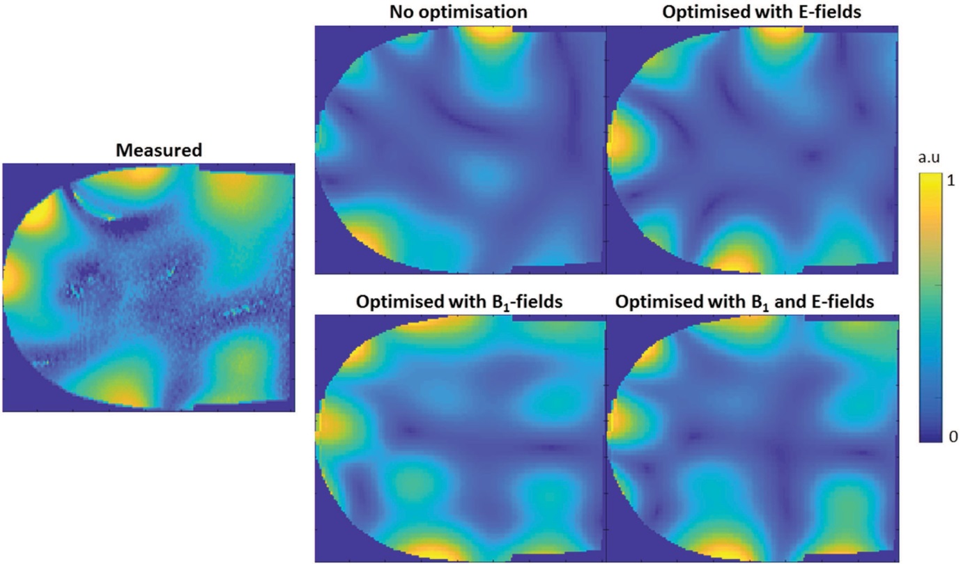
Figure 2 shows POShim 3 as an example of the distribution of E-field along the centre of the empty tube of the phantom with the different correction methods. Large errors were present when no correction of the simulated data was performed, or when the correction was based on B1-fields only. Figure 3 shows a summary of the results for the case of E-fields and show that errors could be significantly reduced by correcting the simulation based on E-field measurements. Similarly, Figure 4 shows a summary of the RMSE between the measured and simulated B1-maps. The different simulation methods had limited effect on the errors between measured and simulated relative B1-maps, with a majority of the RMSE due to errors in the phase components. Poor agreement was achieved between measured and simulated combined B1 profiles when results were not corrected, or using E-field only for correction, while using measured B1-field to correct the simulated data improved the results substantially. An example is shown in Figure 5 for the case of POShim1.Discussion and Conclusion
In this work, results showed that measurements of B1- and E-fields are well suited for the validation of simulations of pTx coils in the presence of a hip implant. Validation of both E-fields and B1-fields was shown to be critical to prevent large errors. Co-simulation method followed by correction of simulated results based on measured E-field and B1 distributions were shown to limit underestimations and overestimations, which were significant in cases where either E-field or B1-field based corrections were neglected. Although this framework was obtained in the case where a metal implant was present in the phantom, they may be generalised to other scenarios and could potentially help to support fast and reliable assessment of RF simulations for pTx coils.Acknowledgements
The study was funded by the National Health & Medical Research Council (NHMRC Program Grant APP1132471) of Australia. We thank and acknowledge Mr Miguel Fuentes, Mr Craig Freakly and Mr Rafael Franco for the construction and design of the phantom used in this study.References
1. Jin J, Weber E, Destruel A et al. An open 8-channel parallel transmission coil for static and dynamic 7T MRI of the knee and ankle joints at multiple postures. Magnetic Resonance in Medicine 2018.
2. Lee J, Gebhardt M, Wald LL et al. Local SAR in parallel transmission pulse design. Magnetic Resonance in Medicine 2012;67(6):1566-1578.
3. Grissom W, Yip CY, Zhang ZH et al. Spatial domain method for the design of RF pulses in multicoil parallel excitation. Magnetic Resonance in Medicine 2006;56(3):620-629.
4. International Electrotechnical Commission: Medical electrical equipment, Part 2: particular requirements for the basic safety and essential performance of magnetic resonance equipment for medical diagnosis 2010.
5. Destruel A, O'Brien K, Barth M et al. Adaptive SAR mass-averaging to predict RF heating for B1 shimming in the presence of a hip implant for parallel transmit at 3T. 2018; Proceedings of the 26th Annual Meeting of ISMRM, Paris, France.
6. Destruel A, O'Brien K, Jin J et al. Adaptive SAR mass-averaging framework to improve predictions of local RF heating near a hip implant for parallel transmit at 7T. Magnetic Resonance in Medicine 2018.
7. Hoffmann J, Henning A, Giapitzakis IA et al. Safety testing and operational procedures for self-developed radiofrequency coils. NMR Biomed 2016;29(9):1131-1144.
8. Destruel A, Fuentes M, Weber E et al. Comparison between experimental and simulated electric fields near a hip implant in a parallel transmit hip coil. 2018; Proceedings of the 26th Annual Meeting of ISMRM, Paris, France.
9. Kozlov M, Turner R. Fast MRI coil analysis based on 3-D electromagnetic and RF circuit co-simulation. J Magn Reson 2009;200(1):147-152.
10. Massire A, Bitz A, Boulant N et al. An 8Tx/8Rx coil validation workflow toward Virtual Observation Points-based parallel transmission cervical spinal cord in vivo imaging at 7T 2017.
11. Beqiri A, Hand JW, Hajnal JV et al. Comparison between simulated decoupling regimes for specific absorption rate prediction in parallel transmit MRI. Magnetic Resonance in Medicine 2015;74(5):1423-1434.
Figures