4167
Specific Absorption Rate in Head-Only Mid-Field Scanner: Comparisons to 1.5 T and 3 T1Physics and Astronomy, University of Western Ontario, London, ON, Canada, 2Synaptive Medical, Toronto, ON, Canada
Synopsis
The mid-field system studied here demonstrates reduced maximum 10-g SAR when performing RF excitation around resonant lead lengths as well as a total reduction in SAR consistent with SAR α Bo2. In comparison to 1.5 T and 3 T clinical scanners, mid-field scanners provide unique opportunities to obtain diagnostically relevant information with a commensurate increase in safety for patients with implanted devices.
Introduction
Patients with implanted medical devices are traditionally excluded from MR imaging or are imaged under highly rigorous FDA safety regulations that can severely limit the clinical utility of the resultant image potentially resulting in insufficient field-of-view (FOV) coverage and several-fold increases in scan duration in clinical 1.5 T scanners [1].
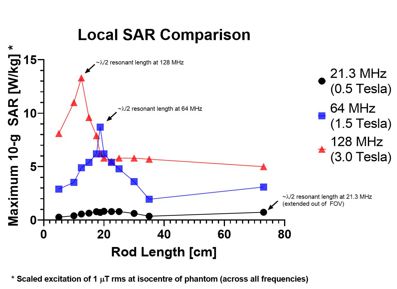
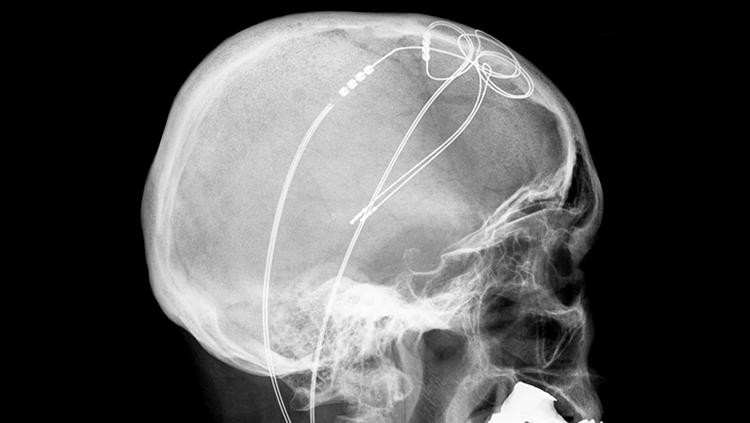
Implants in the presence of an external radio-frequency (RF) field pose the risk of tissue heating due to induced electric currents on implanted devices [2]. Implants of concern include electrically conductive neurostimulator leads that have the potential to resonate at or near the Larmor frequency, resulting in a high local specific absorption rate (SAR) that exceeds the FDA regulation of 10 W/kg [3]. Fig. 1 quantifies the two common problems: (1) achieving a resonant length due to lead geometry (including inductance due to lead coiling, etc.) and (2) orientation with-respect-to the externally applied RF field.
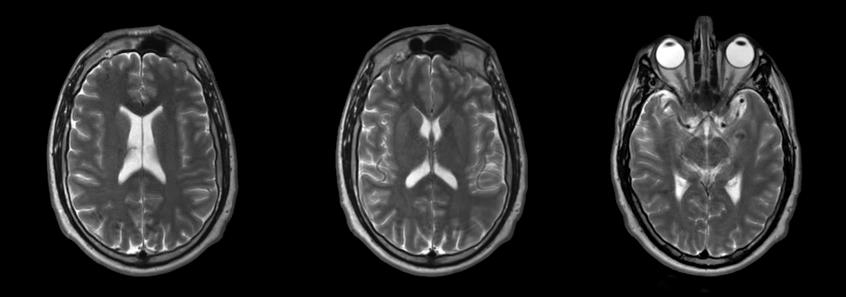
SAR is proportional to the square of the main magnetic field strength – see Fig. 2a for birdcage coils operating at 0.5 Tesla, 1.5 Tesla, and 3.0 Tesla. While imaging at lower field strengths (< 1.0 T) reduce patient risk due to device RF heating, historically such mid-field scanners have suffered from lower achievable signal-to-noise ratio (SNR) compared with higher-field scanners. However, as demonstrated in Fig. 3 recent strides in mid-field technology have increased the clinical utility of a mid-field head-only scanner to be comparable to currently available 1.5 T scanners. Thus, studies on safety for patients with implanted devices are warranted for mid-field systems.
Methods
This study investigates the resonant lengths corresponding to 21.3 MHz, 64 MHz, and 128 MHz, for a head-only birdcage coil. The simulation geometry is shown in Fig. 2b.
Parametric simulations were performed with CST Microwave Studio 2018 using the full-wave time-domain solver with a 12-leg ‘high-pass’ birdcage volume coil: 39.7-cm in diameter and 35-cm long. A phantom (dimensions: 9 x 35 x 35 cm) was placed inside the birdcage coil (εr = 80). Embedded in the phantom was a 0.254-mm perfect electrical conducting (PEC) rod with an overall length ranging from 5-cm to 80-cm. Two simulation studies were performed:
(1) Rod lengths were stepped between 5-cm to 35-cm in 5-cm increments, with additional lengths selected around λ/2 resonances corresponding to 64 MHz and 128 MHz. The rod length of 72.5-cm corresponding to the λ/2 resonance of the rod at 21.3 MHz extended outside the FOV of the birdcage. For this simulation, phantom dimensions were 6 x 35 x 85 cm. This physically represented an implant extending into the torso.
(2) A total rod length of 30-cm plus two 3.2 uH in-series inductors - corresponding to an effective 21.3 MHz resonant length enclosed in the birdcage FOV.
Rod placement was determined according to the ASTM F2182011a guidelines whereby the area of worst-case implant orientation, located at least 2-cm from phantom boundaries, was determined. Mesh density located 2-cm around the rod was fixed for all simulation runs, ensuring equal discretization of the rod when comparing individual simulations. All simulations were normalized to produce a B1+ rms =1 μT at the isocenter of the phantom.
Results & Discussion
Visible in Fig. 4 and Fig. 5 is a demonstrably lower 10-g local SAR for 21.3 MHz across all lengths - resonant and non-resonant. According to the simulations, 10-g local SAR at 21.3 MHz does not suffer the same fractional increase in power deposition as is visible at 1.5 T and 3.0 T. We hypothesize the reduced electric field present at 0.5 T is a proportionally greater effect than the reduction in reactance occuring at resonance.
A representative 35-cm birdcage coil, operating at clinical 1.5 T and 3.0 T field strengths, is amenable to exciting λ/2 resonant lengths for 64- and 128-MHz conductors. However, the ~ 75 cm long rod could not be ‘folded’ into the entire 35-cm FOV. Therefore, reducing rod exposure to tangential electric fields results in reduced power deposition, even when the rod is resonant. Interestingly, even when resonance was enforced via lumped element placement on the rod at 21.3 MHz, maximum 10-g SAR at 21.3 MHz was appreciably lower than non-resonant lengths for 1.5 and 3.0 T, respectively.
Nominal safety precautions for neurostimulator implants come in several forms: 0.1 W/kg whole-brain SAR and average B1+ field maximums [4]. The authors note that the 2.0 μT average field metric would cause both 1.5 T and 3.0 T scanners to exceed the 10 W/kg local SAR limits, however the 0.5 T scanner would appear to be able to run at ~ 10 μT average. Considering low RF duty cycles used during routine pulse sequences, this could allow for substantial increases in peak B1+. Further experiments will test this hypothesis.
Acknowledgements
The authors acknowledge funding received through the MITACS Accelerate Post-Doctoral Fellowship award.References
[1] Franceschi AM, Wiggins GC, Mogilner AY, Shepherd T, Chung S, Lui YW. Optimized, Minimal Specific Absorption Rate MRI for High-Resolution Imaging in Patients with Implanted Deep Brain Stimulation Electrodes. American Journal of Neuroradiology. 2016;37(11):1996-2000. Doi: 10.3174/ajnr. A4865.
[2] Collins CM, Wang Z. Calculation of radiofrequency electromagnetic fields and their effects in MRI of human subjects. Magnetic Resonance in Medicine. 2011;65(5):1470–1482. doi: 10.1002/mrm.22845.
[3] IEC 60601-2-33. Requirements for the safety of MR equipment for medical diagnosis. International Electrotechnical Comission (IEC). 2015.
[4] Shellock FG. Magnetic Resonance Safety Update 2002: Implants and Devices. Journal of Magnetic Resonance Imaging. 2002; 16:485-496.
[5] Retrieved from: Wikimedia Commons. Nov. 6, 2018. Credit: Hellerhoff, CC BY-SA.
Figures
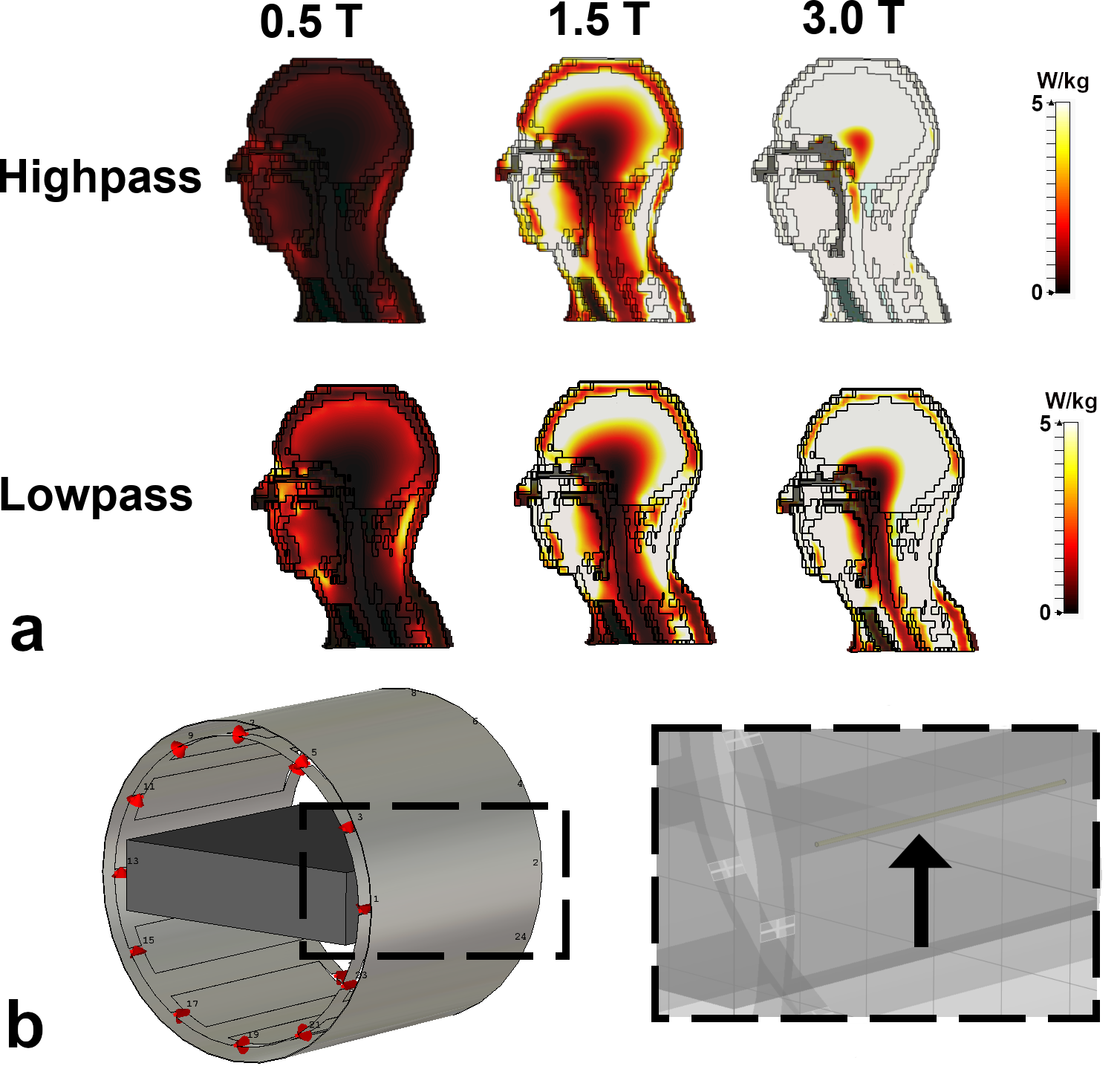
(a) Bo-dependence of 10-gram SAR. Excitation was performed with the 12-leg 'high-pass' birdcage coil described in the Methods. 10-gram SAR was computed across a representative sagittal slice of voxel model 'Gustav' in full-wave time-domain software.
(b) Simulation setup in CST. Left: 12-leg birdcage with shield and phantom. Right: Embedded rod is visible in the phantom.