4164
RF Safety of EEG gel during MRI: a case study1Max Planck Institute for Human Cognitive and Brain Sciences, Leipzig, Germany
Synopsis
We evaluated the influences of the EEG gel on RF safety assessment of a 3T whole body scanner with a human subject located at a head landmark position. Our case study, which was performed assuming realistic conditions that may occur with commercially available equipment, provides evidence that the EEG gel “helmet” has an impact on head SAR during 3T MRI for a patient positioned at the head landmark position. A workaround for safe simultaneous EEG-MRI investigations might involve limiting the maximum transmit voltage at a lower level than that allowed by the scanner’s SAR supervision system (i.e. that for a given patient without EEG gel “helmet”).
Introduction
An increasing number of MRI investigations of the human brain employ multi-modal setups, where additional devices (e.g., EEG, TMS, tDCS) are used to record complementary information or to manipulate brain states. In the case of electroencephalography (EEG) this requires dozens of electrodes placed on the scalp, conductive gel, and wires to connect electrodes with a receiver. RF-induced heating in the area surrounding EEG electrodes has been the primary safety concern1. A potential modification of electromagnetic (EM) field inside human head due to conductive EEG gel covering a large fraction of the scalp has previously been neglected. Goal of the study was to evaluate the influences of the EEG gel for RF safety assessment of a 3T whole-body scanner with a human subject located at the head landmark position.Methods
The simulated whole-body coil was a 123.2 MHz 16-rung high-pass birdcage of equivalent design as widely used in clinical 3T scanners. The NEVA Electromagnetics high-resolution human model2 was used as a load with scaling factor 0.9 and electrical properties of tissues adopted from the IT’IS database3 (Fig.1). The model head was positioned in the coil’s isocenter. The coil was shielded by a metal enclosure that mimicked a 1220mm-long scanner bore. The coil was tuned, matched, and decoupled using an elliptical phantom (length 700mm, major radius 175mm, minor radius 95mm) positioned in the isocenter of the coil. The evaluation was based on a co-simulation approach including both RF-circuit (Keysight_ADS2016) and 3D-EM (ANSYS_HFSS) simulations. The amplitudes of RF sources used to excite the coil were the same for both feeds with a 90° phase shift between the feeds as in quadrature excitation. The EEG gel setup was modeled as a "helmet" with 2 mm thickness (Fig.1c-d). Three types of commercial gels, namely Abralyt2000 (Electrolyte-Gel for ActiveShield Cap or Electro-cap; chloride-free [4]), Abralyt HiCL (high-chloride electrode gel [5]), ECI electro-gel for electro-caps (Electro-Cap International, Inc., Eaton, OH, USA) [6], were simulated as a conductive medium with εr={73,50,45} and σ={2.2,7.5,9.6}S/m, respectively. All results are presented for 2W transmit power.Results and Discussion
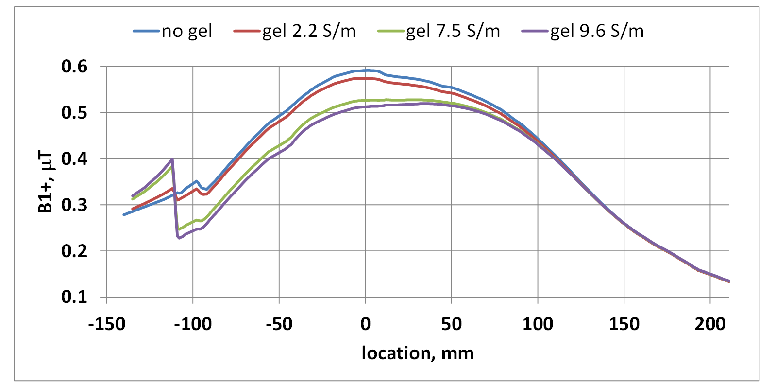
The circuit level optimization resulted in a properly tuned coil (Figs.2a). However, when the coil was loaded by the human model, the S-parameters were visibly affected (Figs.2b). Results obtained without an EEG gel “helmet” were consistent with literature reports7: B1+ was rather homogeneously distributed across the head, and the power deposition showed a maximum in the neck region (Figs.3a-b). Upon adding the EEG gel “helmet”, substantial power deposition was observed in the gel as well as in close proximity of the “helmet” edges for all types of gels (Fig. 3 c-f). Simultaneously, power deposition at top part of intercranium region was slightly decreased. The B1+ disturbance in the head region increased with increasing gel conductivity. Higher gel conductivity resulted in decreased B1+ at the coil isocenter and in the upper parts of the head (Figs.4-5). B1+ and power deposition below neck as well as coil S-parameters were not significantly affected by the gel “helmet”. The latter means that the scanner’s SAR supervision system cannot detect the appearance of the gel “helmet”. Consequently, the SAR supervision system considers that the safe level of B1+ remains at the initial level. However, MRI scans with the same B1+ level and gel “helmets” of Abralyt2000, Abralyt HiCL, and ECI electro-gels resulted in 106%, 126%, and 136% of head SAR (as compared to the situation without additional gel), respectively (Fig.5). We cannot safely exclude that obtained range of head SAR increases are higher than the safety margin of a scanner’s SAR supervision system. This rises a potential safety concern for EEG measurements in 3T whole-body scanners, especially if high-conductivity EEG gels are used.Conclusion
Our case study provides evidence that the EEG gel “helmet” has an impact on head SAR during 3T MRI for a patient positioned at head landmark position. Use of EEG gel is not explicitly considered in the procedures that are implemented for SAR monitoring on MRI scanners. A workaround for safe simultaneous EEG-MRI investigations might involve limiting the maximum transmit voltage at a lower level than that allowed by the scanner’s SAR supervision system (i.e. that for a given patient without EEG gel “helmet”). The voltage reduction ratio can be derived from the ratio of B1+ at the coil isocenter for the patient (a) without and (b) with the gel helmet if the transmit voltage of the whole-body coil is fixed. While our results were derived assuming realistic conditions that may occur with commercially available equipment, it is to note that cannot be easily readily generalized because only a single coil geometry, one thickness of gel “helmet” and a single human model were included in our investigation.Acknowledgements
The authors thank Frank Seifert (Physikalisch-Technische Bundesanstalt, Berlin, Germany) for the discussions and gel measurements.References
[1] L. Kuusela, S. Turunen, L. Valanne and O. Sipila, “Safety in simultaneous EEG-fMRI at 3T: temperature measurements”, Acta Radiologica 2015, Vol. 56(6) 739–745, DOI: 10.1177/0284185114536385.
[2] J. Yanamadala, G. M. Noetscher, V. K. Rathi, S. Maliye, H. A. Win, A. L. Tran, X. J. Jackson, A. T. Htet, M. Kozlov, A. Nazarian, S. Louie, S. N. Makarov, “New VHP-Female v. 2.0 Full-Body Computational Phantom and Its Performance Metrics Using FEM Simulator ANSYS HFSS,” 37th Annual Int. Conf. of the IEEE Eng. in Medicine and Biology Society, Milano, Italy, Aug. 25-29, 2015, pp. 3237-3241.
[3] www.itis.ethz.ch/database. Hasgall PA, Di Gennaro F, Baumgartner C, Neufeld E, Gosselin MC, Payne D, Klingenböck A, Kuster N, “IT’IS Database for thermal and electromagnetic parameters of biological tissues,” Version 3.0, September 1, 2015.
[4] https://www.easycap.de/wordpress/wp-content/uploads/2018/02/ImpedancesElectrolytes.pdf
[5] https://www.rogue-resolutions.com/catalogue/accessories/abralyt-hicl-eeg-electrode-gel/
[6] https://bio-medical.com/electro-gel-for-electro-caps.html
[7] D. Yeo, Z. Wang, W. Loew, M. Vogel, and I. Hancu, “Local SAR in High Pass Birdcage and TEM Body Coils for Multiple Human Body Models in Clinical Landmark Positions at 3T”, J Magn Reson Imaging. 2011 May ; 33(5): 1209–1217. doi:10.1002/jmri.22544.
Figures