4163
RF heating of an intracranial pressure sensor in a 64 MHz head-only RF coil: a simulation study1Physics and Astronomy, University of Western Ontario, London, ON, Canada
Synopsis
Heating of implanted medical devices is a well-known hazard in MRI. We evaluated a device which represents an intracranial pressure sensor device, in which a catheter would be inserted into the cranium while the remainder of the catheter and device would be outside the skull, possibly under the skin. The device was modeled as a PEC with a fixed length and was positioned with a variable amount of the lead within the brain and exposure to a 64 MHz head-only RF coil. We found the heating is highest when the amount of the lead within the brain is minimized.
Introduction
Heating of implanted medical devices is a well-known hazard in MRI1-3.In particular, implanted devices with extended, loose leads have the potential to strongly couple to RF fields within the body and result in dangerous heating levels at either 64 or 128 MHz. ISO 10974:2018(E) is a relatively new test standard to guide testing and evaluation of active implantable medical devices, and a large portion of that standard is dedicated to the evaluation of heating in devices with leads4. A first stage in the evaluation of any device system for RF heating is to determine, via computer simulations or other means, what the worst-case configuration(s) of the device(s) are. The computer simulation process is generally an exhaustive one, and any consistent trends in the response of devices to RF exposure are highly valuable as they allow a reduction in the required simulation parameter space. One class of device that is particularly difficult to evaluate is a device that has only a portion of a lead implanted, and the remainder outside the body. In this study, we evaluated a simplified device which represents an intracranial pressure sensor device, in which a catheter would be inserted into the cranium while the remainder of the catheter and device would be outside the skull, possibly under the skin. The simple question we sought to answer was: for a fixed lead length and exposure to a 64 MHz head-only RF coil, is the worst-case configuration that with the maximum amount of lead within the brain, the minimum amount in the brain, or something in between?Methods
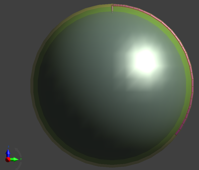
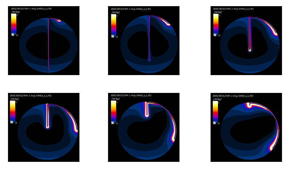
The head was modeled as a three-component spherical structure. The brain was approximated as a uniform sphere of 80 mm radius, mass density of 1050 kg/m^3, electrical conductivity of 0.72 S/m, and relative permittivity of 116. The layer surrounding the brain was “bone” with thickness of 5 mm, mass density of 1180 kg/m^3, electric conductivity of 0.082 S/m, relative permittivity of 16.7. The outermost layer was “skin” with thickness of 3 mm, mass density of 1109 kg/m^3, electric conductivity of 0.436 S/m, relative permittivity of 92. The device was modeled as a 0.75 mm diameter PEC that had a total fixed length of 200 mm and was positioned with a variable amount of the lead within the brain (6 different cases, with between 2 mm and 160 mm within the brain) and the remaining portion running under the skin but outside the skull (bone). The simulation was conducted for both insulated (insulation thickness of 0.5 mm, exposed end of 2 mm, relative permittivity of 3) and non-insulated lead. A schematic of the simulation with brain, skull, skin, and device is shown in Figure 1. The 6 configurations simulated are shown in Figure 2 (along with the simulation results).
The RF coil was modeled as a shielded, Circularly-polarized head-only 64 MHz cylindrical RF coil, with 16 equally spaced rungs, radius of 145 mm, and length of 384 mm. The diameter of shield was 400 mm with a length of 500 mm. The current in the rungs was set such that B1+ in the center volume of the brain would be 1 µT when no device was present.
Results
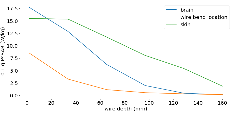
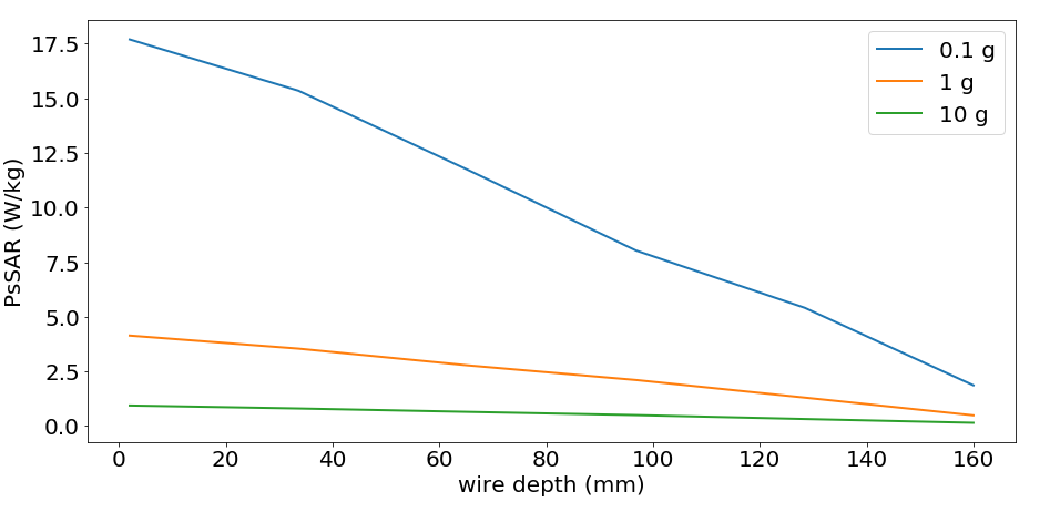
The results for 0.1 g spatial averaged SAR along a YZ slice at the location of the wire is shown in Figure 2. The Peak spatial averaged SAR (PsSAR) over 0.1 g of tissue at three different regions (tip of the wire in the brain, the end of the wire under the skin, and the wire bend location) is shown in Figure 3. The peak averaged SAR over 0.1g, 1 g and 10 g of tissue (maximum value anywhere within the head) is shown in Figure 4. As expected, the heating increased (in all regions) as more of the wire was positioned along the outside of the skull, underneath the skin.Conclusion
Although much more work (both in simulation of additional configurations and orientations, as well as validation of the simulations) is required, this simple simulation study suggests that for devices with a portion of the lead within the brain and the other portion implanted outside the skull but under the skin, the heating is highest when the amount within the brain is minimized. This can help to guide more complicated simulations and possibly guide the simulation parameter space, enabling more simulation efforts to be directed to other parameters where the effects are less clear. Expansion of this study to 128 MHz (3 T) head-only RF coils is also an obvious avenue for future work.Acknowledgements
We acknowledge financial support from NSERC and the Ontario Research Fund.References
1. E. Mattei et al., Complexity of MRI induced heating on metallic leads: Experimental measurements of 374 configurations, Biomed. Eng. Online., vol. 7, Mar. 2008, Art. no. 11.
2. J. A. Nyenhuis, A. V. Kildishev, J. D. Bourland, K. S. Foster, and G. Grabber,Heating near implanted medical devices by the MRIRF-magnetic field, IEEE Trans. Magn., vol. 35, no. 5, pp. 4133–4135, May 1999.
3. A. R. Rezai, D. Finelli, J. A. Nyenhuis, G. Hrdlicka, J. Tkach, A. Sharan, P. Rugieri, P. H. Stypulkowski, and F. G. Shellock, Neurostimulation systems for deep brain stimulation: Invitro evaluation of magnetic resonance imaging-related heating at 1.5 telsa, J. Magn. Reson. Imag., vol. 15, pp. 241–250, 2002.
4. ISO/TS 10974. Assessment of the safety of magnetic resonance imaging for patients with an active implantable medical device; 2018.
Figures