4160
B1+ Peak Based on Transmit Technologies and the Impact of Associated E Fields on AIMD MR RF Safety1Abbott, Sunnyvale, CA, United States, 2Abbott, Sylmar, CA, United States
Synopsis
Circular polarization (CP), Linear Polarization (LP) and Multi-Channel-N (MC-N) are RF transmit technologies at 3T. The B1+ peak limit is dependent on the RF coil amplifier topology and the transmit scheme. This may lead to significant changes in the induced E field in a patient and affect the MR safety assessment for active implantable medical devices (AIMDs). This abstract shows that even though B1+ peak levels of LP is lower than that of CP or MC-N, the E-field along an implant during LP can exceed CP or MC-N. Therefore, since LP can be achieved within CP or MC-N, it should be considered for AIMD MR safety assessment.
Introduction
3T and above MR systems utilize three transmit schemes: 1) Linearly Polarized (LP), commonly applied during pre-scan; 2) Circularly Polarized (CP), commonly known as quadrature; 3) Multichannel-N (MC-N), which includes B1 shimmed systems. This paper investigates the B1+ peak levels and associated E-fields of the three transmit technologies and the impact to AIMD MR safety assessment.Methods
Transmit technologies are defined as:
- Linear Polarization (LP): The B1+ field in the center of RF coil where the dominant amplitude variations are along a single axis in a plane orthogonal to the static field.
- Circular Polarization (CP): The B1+ field in the center of RF coil where the field vector describes a circular trajectory in a plane orthogonal to the static field.
- Multi Channel-N (MC-N, N = 2,3,…): RF transmission where N independent waveforms are fed into RF coil with N >= 2.
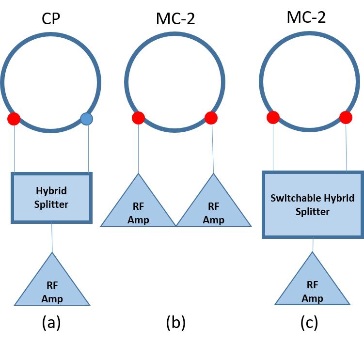
In this abstract, the focus is 2-port body coils. The designs can be categorized into two fundamental configurations: RF power amplifier with hybrid splitter to construct CP or MC-2(Figure 1(a), (c)), and independent RF power amplifiers to construct MC-2 (Figure 1 (b)). LP may occur at each independent port (shown as red circles in Figure 1) during the pre-scan for any configuration. To compare the maximum B1+ peak level at hardware limit of MR scanners in CP, LP and MC-2 for each configuration in Figure 1, we assume: 1) maximum peak delivered power is applied to one of the RF amplifiers, 2) the hybrid splitters are lossless, 3) there is perfect impedance matching and negligible coil loss.
To construct LP, CP and MC-2, electromagnetic (EM) fields in human models for each port is simulated with Sim4Life1 and then combined to produce each transmit technology. Both ports (denoted as I port and Q port) are simulated separately for Duke model from V3 Virtual Population2 in a 70cm diameter 3T RF body coil at thoracic imaging position. As suggested by Murbach et al3, an amplitude ratio of 0.5, 1, 1.5 and phase difference of 45°, 90°, and 135° for MC-2 RF shimming were used. After EM field combination, the B1+ field in the human body, averaged over isocenter plane, was calculated per IEC 60601-2-334.
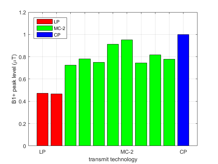
For independent RF amplifiers (Figure 1 (b)), the same peak power was delivered to each port at CP, then the maximum B1+ peak level of CP was normalized to 1µT. The LP and MC-2 cases follow the same normalization factor.
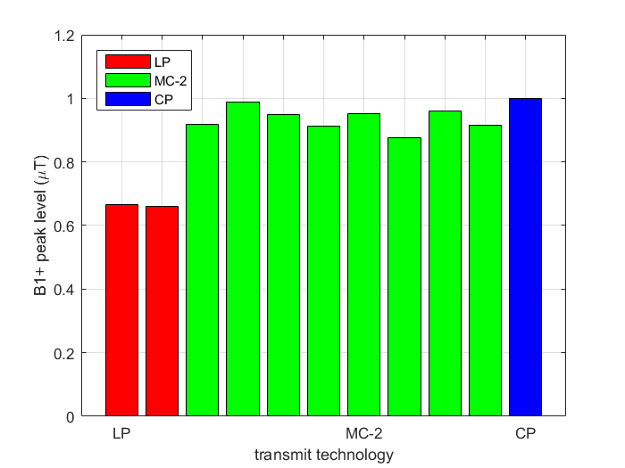
For single RF amplifier (Figure 1 (a), (c)), the maximum power for the RF amplifier was delivered for LP, CP and MC-2 cases. The B1+ peak levels were normalized to 1µT for CP scenario. The LP and MC-2 cases are normalized using the same total delivered power.
Results
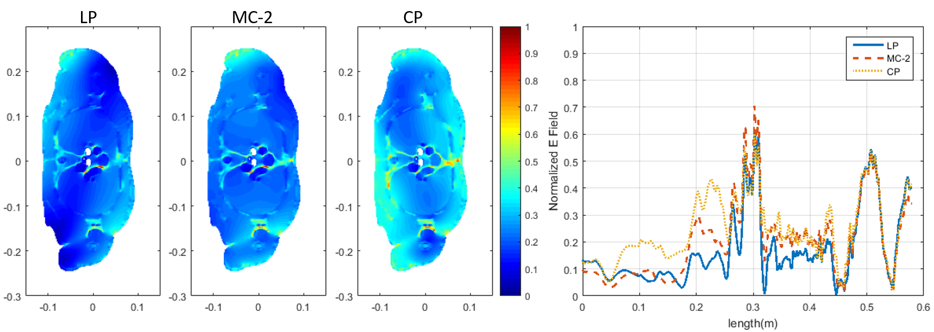
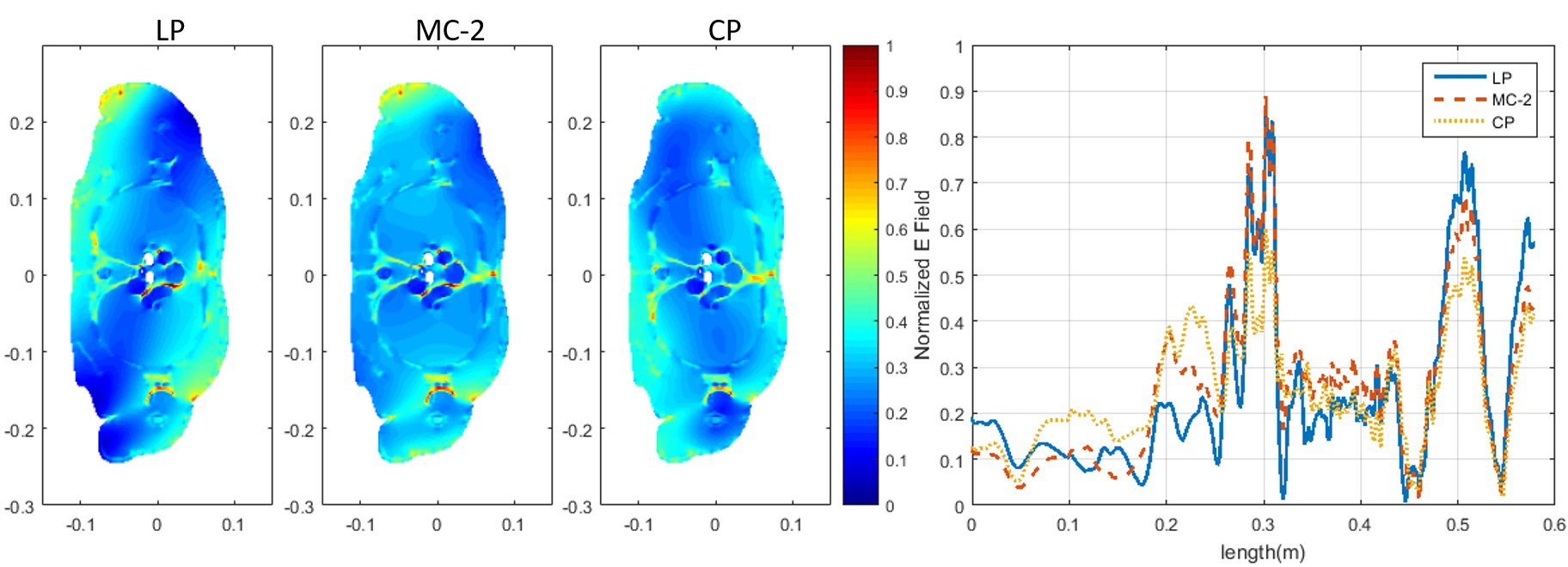
If the independent RF amplifiers (Figure 1 (b)) are applied, the B1+ peak levels are plotted in Figure 2. To show the impact of B1+ peak level on E field distribution, we choose amplitude 0.5 and phase 45° for MC-2. The E field distributions at isocenter plane and Etan along a typical cardiac pathway for each transmit technology are shown in Figure 3.
If single RF power amplifier with switchable hybrid splitter (Figure 1 (a) and (c)) is used, the B1+ peak levels are plotted in Figure 4. Figure 5 shows the E field distributions at isocenter plane and along a typical cardiac pathway for each transmit technology.
Discussion
B1+ peak levels from LP can be lower than that of CP and MC-2 in line with previous finding5. However, in the case of the single RF power amplifier, the changes in E field distributions were enough for the Etan along an implant pathway for LP to exceed CP and MC-2.
Conclusion
The B1+ peak levels for LP may be as low as half of the B1+ peak levels for CP, and therefore the scaling factor to generate a peak E-field for implant safety assessment may also be reduced for LP. However, depending on transmit implementation, the reduction in the scaling factor may not be enough to guarantee the E-field along an implant due to LP will not exceed the E-field due to CP or MC-2. Since LP may be achieved in CP or MC-2, LP transmit technology should be considered during 3T MR safety assessment on AIMDs.Acknowledgements
No acknowledgement found.References
- Sim4Life. https://zmt.swiss/sim4life/
- Gosselin MC, Neufeld E, Moser H, et al. Development of a new generation of high-resolution anatomical models for medical device evaluation: the Virtual Population 3.0. Physics in Medicine & Biology. 2014; 59(18):5287-303
- Murbach M, Neufeld E, Cabot E, et al. Virtual population‐based assessment of the impact of 3 Tesla radiofrequency shimming and thermoregulation on safety and B1 + uniformity. Magn Reson Med 2016;76:986–997.
- IEC 60601-2-33:2010, Medical electrical equipment - Part 2-33: Particular requirements for the basic safety and essential performance of magnetic resonance equipment for medical diagnosis; 2010
- Glover, et al. Comparison of Linear and Circular Polarization for Magnetic Resonance Imaging. J. Mag Res 1985; 64: 255-279.
Figures