4004
Extended phase graph framework for "inhomogeneous" MT systems.1Biomedical Engineering Department, School of Biomedical Engineering and Imaging Sciences, King's College London, London, United Kingdom, 2Centre for the Developing Brain, School of Biomedical Engineering and Imaging Sciences, King's College London, London, United Kingdom
Synopsis
Recently, the extended phase graph with exchange (EPG-X) formalism has been introduced for modelling magnetization transfer (MT) effects during arbitrary pulse sequences. Here, we present a further extension to include a dipolar order component of the macromolecular (i.e. semisolid) pool, as has been proposed to understand the “inhomogeneous” MT (ihMT) contrast mechanism observed in ordered structures such as myelin and muscle. Preliminary results demonstrate the flexibility of the developed simulation tool for ihMT contrast optimisation and the investigation of steady-state sequence dynamics.
Introduction
“Inhomogeneous” magnetization transfer (ihMT) is an endogenous contrast mechanism that appears more specific to myelinated tissue compared to standard MT imaging, and therefore shows potential for the assessment of neurological conditions.1,2 Contrast is obtained by comparing MT-weighted experiments at equal radiofrequency (RF) power using single frequency and symmetric dual-frequency off-resonance irradiation.Theory
In ihMT modelling, tissue is assumed to comprise free water (f) and semisolid protons (s); the latter have both Zeeman (Z) and dipolar (D) order.3 The evolution of magnetization is described by:
$$\dot{\boldsymbol{M}}=(\boldsymbol{\Omega}+\boldsymbol{\Lambda})\boldsymbol{M}+\boldsymbol{C}\space$$
$$\boldsymbol{\Omega}=\begin{bmatrix}&&&0&&0\\&\boldsymbol{\Omega_{free}}&&0&&0\\&&&0&&0\\0&0&0&&&\\&&&&\boldsymbol{\Omega_{semi}}&\\0&0&0&&&\end{bmatrix}\space\space\boldsymbol{\Lambda}=\begin{bmatrix}-R_{2}^{f}-i\delta\omega&0&0&0&0\\0&-R_{2}^{f}+i\delta\omega&0&0&0\\0&0&-KM_{0}^{s}-R_{1}^{f}&KM_{0}^{f}&0\\0&0&KM_{0}^{s}&-KM_{0}^{f}-R_{1Z}^{s}&0\\0&0&0&0&-R_{1D}^{s}\end{bmatrix}$$
$$\boldsymbol{C}=\left[\begin{array}{c}0\space\space\space\space 0\space\space\space\space R_{1}^{f}M_{0}^{f}\space\space\space\space R_{1Z}^{s}M_{0}^{s}\space\space\space\space 0\end{array}\right]^{T}$$
The magnetization vector is: $$$\boldsymbol{M}=[M_+^f\space\space\space\space M_-^f\space\space\space\space M_z^f\space\space\space\space M_Z^s\space\space\space\space M_D^s]^T$$$, where $$$M_D^s$$$ represents dipolar spin order, $$$R_1$$$ and $$$R_2$$$ are longitudinal and transverse relaxation rates respectively and $$$K$$$ is an inter-pool exchange rate. Matrix $$$\boldsymbol{Λ}$$$ describes free pool precession and contains both relaxation and exchange terms, whereas matrix $$$\boldsymbol{Ω}$$$ describes RF effects and comprises:
$$\boldsymbol{\Omega_{free}}=\begin{bmatrix}0&0&i\omega_{1+}\\0&0&-i\omega_{1+}^*\\\frac{i}{2}\omega_{1+}^*&-\frac{i}{2}\omega_{1+}&0\end{bmatrix}\space\space\boldsymbol{\Omega_{semi}}=\sum_\Delta\begin{bmatrix}-W(\Delta)&W(\Delta)\frac{\Delta}{\omega_{loc}}\\W(\Delta)\frac{\Delta}{\omega_{loc}}&-W(\Delta)(\frac{\Delta}{\omega_{loc}})^{2}\end{bmatrix}$$
$$$\Omega_{free}$$$ is written in the basis $$$\omega_{1+}=\gamma(B_{1,x}+iB_{1,y})$$$ and $$$\Omega_{semi}$$$ describes semisolid pool energy absorption at a rate: $$$W(\Delta)=\pi\gamma^{2}B_{1}^{2}g(\Delta)$$$. $$$g$$$ is the absorption lineshape (super-Lorentzian for semisolids) at off-resonance frequency $$$\Delta$$$, and $$$\omega_{loc}$$$ is local field fluctuation strength.
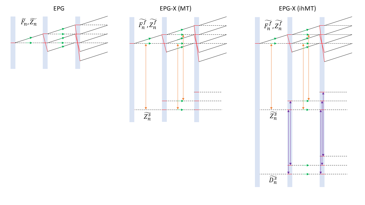
The original extended phase graph with exchange (EPG-X)4 publication shows how to transform to an EPG representation by splitting transverse and longitudinal components and taking Fourier transforms. Transverse components, $$$\boldsymbol{F_{n}}=[\tilde{F_{n}^{f}}\space\space\space\space\tilde{F_{-n}^{*f}}]^T$$$ are unchanged, as are state evolution rules (shift and relaxation operators, $$$\boldsymbol{\Psi}$$$ and $$$\boldsymbol{\Xi_{T}}$$$). However, consideration of dipolar order requires an additional ‘longitudinal’ state, $$$\tilde{D_{n}^{s}}$$$ such that: $$$\boldsymbol{Z_{n}}=[\tilde{Z_{n}^{f}}\space\space\space\space\tilde{Z_{n}^{s}}\space\space\space\space\tilde{D_{n}^{s}}]^{T}$$$. The longitudinal relaxation-exchange operator is modified to include dipolar order effects for a dephasing time, $$$\Delta t$$$:
$$\boldsymbol{\Xi_{L}}=exp\left(\begin{bmatrix}-KM_{0}^{s}-R_{1}^{f}&KM_{0}^{f}&0\\KM_{0}^{s}&-KM_{0}^{f}-R_{1Z}^{s}&0\\0&0&-R_{1D}^{s}\end{bmatrix}\Delta t\right)$$
Following RF pulse application, states of a given order n are mixed according to a transition operator, $$$\boldsymbol{T}$$$:
$$\boldsymbol{T}=\begin{bmatrix}&&&0&&0\\&\boldsymbol{T_{classic}}&&0&&0\\&&&0&&0\\0&0&0&&&\\&&&&e^{\boldsymbol{\Omega_{semi}}\tau}&\\0&0&0&&&\end{bmatrix}$$
Here, $$$\boldsymbol{T_{classic}}$$$ is the normal free pool transition matrix used by EPG, and the other term handles saturation and RF-driven exchange between Zeeman and dipolar semisolid pools. Note, $$$W(\Delta)$$$ is replaced by $$$\bar{W(\Delta)}=\pi\gamma^{2}B_{1,rms}^{2}g(\Delta)$$$ in $$$\boldsymbol{\Omega_{semi}}$$$ and $$$\tau$$$ is RF pulse duration.
As for standard EPG5 and more recent EPG-X methods, we make some assumptions: (i) instantaneous rotation of free pool magnetisation, (ii) relaxation and exchange occur over the entire sequence repetition time (TR) and (iii) RF saturation/exchange in the semisolid pool is applied instantaneously but at a rate determined by root-mean-square $$$B_{1,rms}$$$ applied during $$$\tau$$$. Figure 1 summarises the algorithm and shows the additional pool, $$$\tilde{D_n^s}$$$ that only exchanges with $$$\tilde{Z_n^s}$$$ and only during periods of (off-resonant) RF saturation.
Methods
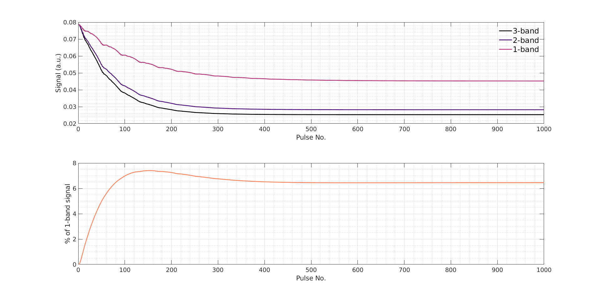
We simulated spoiled gradient-recalled (SPGR) echo and balanced steady-state free precession (bSSFP) sequences comprising repeated multiband (2-band or 3-band)6 pulses. In each case, on-resonance bands flip free pool magnetization, while off-resonant bands only interact with semisolid protons. 3-band pulses are symmetric ($$$-\Delta$$$,0,$$$\Delta$$$) and so no semisolid pool dipolar-Zeeman coupling is expected, unlike for 2-band pulses (0,$$$\Delta$$$). Simulated tissue parameters were from Varma et al. (internal capsule)7, $$$B_{1,rms}^{Seq}$$$ for the whole sequence was limited to 5μT and acquisition parameters were: $$$\alpha$$$ = 5˚ (SPGR) or 25˚ (bSSFP), $$$\tau$$$ = 2ms, TR = 5ms and $$$\Delta$$$ = 8kHz.
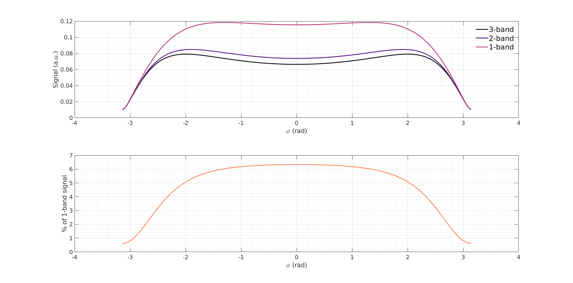
To explore the theory presented above, we examined steady-state behaviour of both sequences, SPGR EPG diagrams and bSSFP sub-voxel magnetization distributions; the latter are constructed by taking inverse Fourier transforms of configuration state populations.
Results and Discussion
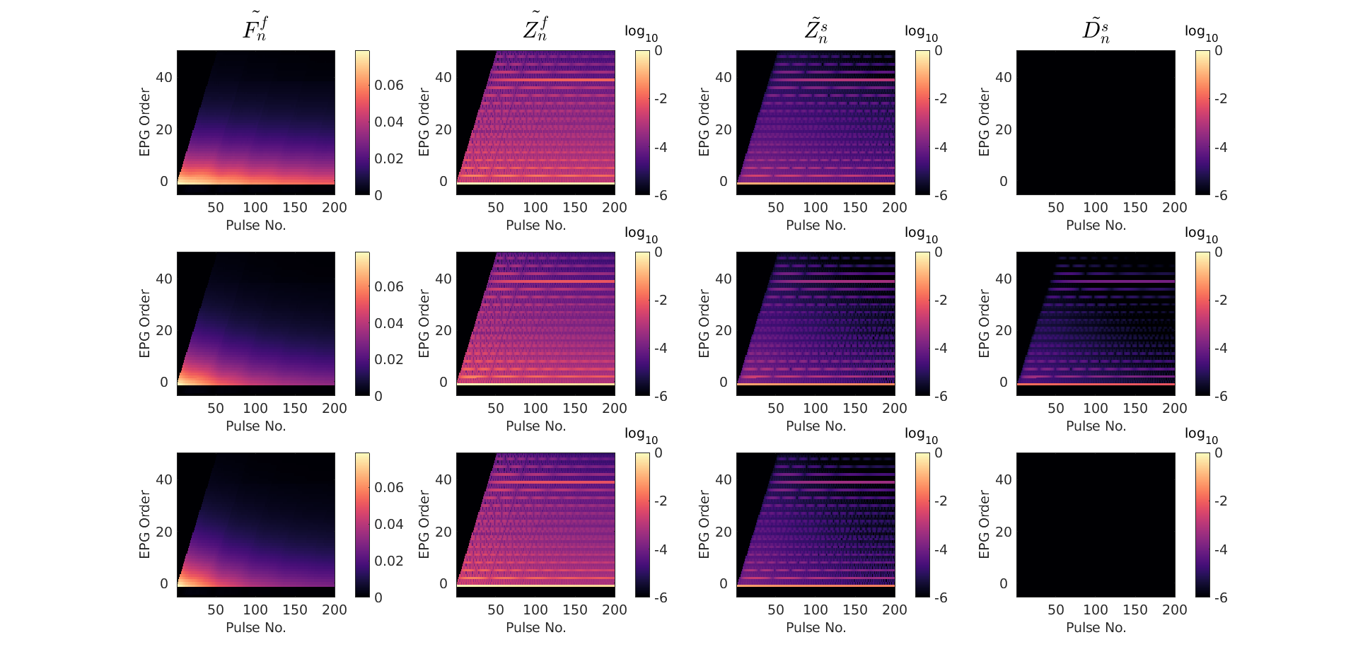
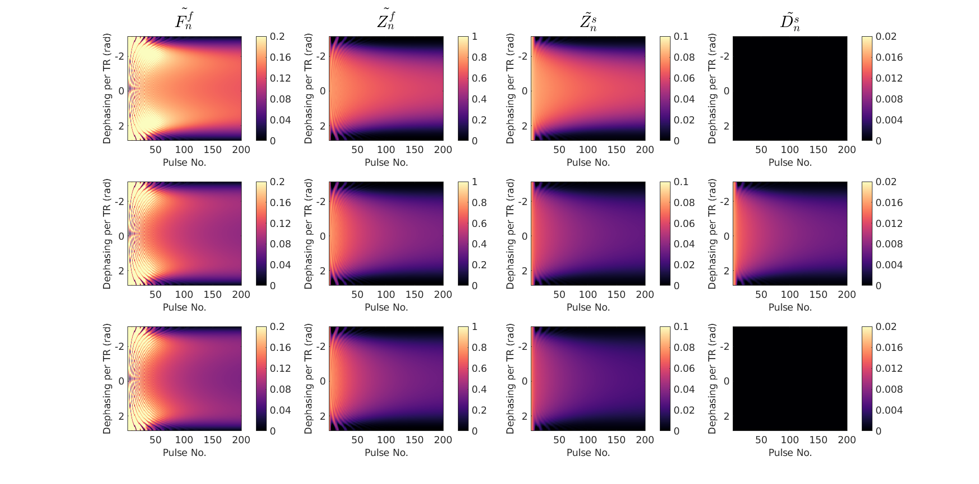
Following implementation of the framework, simulation of SPGR and bSSFP sequences yields expected approaches to steady-state and off-resonance profiles respectively. Using the stated acquisition parameters, SPGR provides a maximum obtainable contrast of 7.4% and bSSFP provides 6.3%. Note, different, reasonable flip angles have been used to simulate these two sequences and so results are not directly comparable. Figure 4 shows SPGR EPG diagrams for each configuration state; non-zero dipolar order exists only when single frequency off-resonance is applied but this is not constant across EPG orders, showing how ihMT contrast interacts with coherences in a rapid MRI sequence. We reconstruct off-resonance magnetization profiles for bSSFP (Figure 5); the familiar ‘banding’ pattern is ‘imprinted’ onto semisolid Zeeman and dipolar ordered components in the 2-band case.
Conclusions
We have presented an EPG framework to model systems with dipolar ordered magnetization that facilitates efficient and adaptable simulation of ihMT contrast. Examining SPGR and bSSFP cases where 2-band pulses are used (i.e. the dipolar pool is populated), shows that the magnetization distribution in the dipolar ordered pool is complex and closely linked to that in the free and semisolid Zeeman pools. Hence, modelling of this type may be necessary to fully characterise an ihMT system when using rapid steady-state pulse sequences. We hope to use this simulation tool to determine an optimal acquisition strategy to provide high myelin sensitivity.Acknowledgements
This work is funded by the King’s College London & Imperial College London EPSRC Centre for Doctoral Training in Medical Imaging (EP/L015226/1). This work was supported by the Wellcome EPSRC Centre for Medical Engineering at Kings College London (WT 203148/Z/16/Z) and by the National Institute for Health Research (NIHR) Biomedical Research Centre based at Guy’s and St Thomas’ NHS Foundation Trust and King’s College London. The views expressed are those of the authors and not necessarily those of the NHS, the NIHR or the Department of Health.References
1. Girard, O. M. et al. Magnetization transfer from inhomogeneously broadened lines (ihMT): experimental optimization of saturation parameters for human brain imaging at 1.5 Tesla. Magn. Reson. Med. 73, 2111–2121 (2015).
2. Varma, G., Duhamel, G., De Bazelaire, C. & Alsop, D. C. Magnetization transfer from inhomogeneously broadened lines: a potential marker for myelin. Magn. Reson. Med. 73, 614–622 (2015).
3. Varma, G. et al. Interpretation of magnetization transfer from inhomogeneously broadened lines (ihMT) in tissues as a dipolar order effect within motion restricted molecules. J. Magn. Reson. 260, 67–76 (2015).
4. Malik, S. J., Teixeira, R. P. A. G. & Hajnal, J. V. Extended phase graph formalism for systems with magnetization transfer and exchange. Magn. Reson. Med. 80, 767–779 (2018).
5. Weigel, M. Extended phase graphs: Dephasing, RF pulses, and echoes - pure and simple. J. Magn. Reson. Imaging 41, 266–295 (2015).
6. A.G. Teixeira, R. P., Malik, S. J. & Hajnal, J. V. Fast quantitative MRI using controlled saturation magnetization transfer. Magn. Reson. Med. 1–14 (2018). doi:10.1002/mrm.27442.
7. Varma, G. et al. Low duty-cycle pulsed irradiation reduces magnetization transfer and increases the inhomogeneous magnetization transfer effect. J. Magn. Reson. 296, 60–71 (2018).
Figures