3853
A Body-Mounted Robot with Integrated Single Loop Coil for MR-Guided Arthrography1Children's Hospital / SZI, Washington DC, DC, United States, 2Imaging Research Center, Cincinnati Children's Hospital, Cincinnati, OH, United States
Synopsis
The purpose of this project is to streamline the workflow for robotic-assisted MR-guided arthrography by integrating a single loop coil in the base / mounting adapter of the robot. This coil provides sufficient spatial coverage and sensitivity to localize anatomic points of interest and registration fiducials embedded in the robot. Integration of the coil with the robot places the imaging coil as close as possible to the patient and reduces the number of devices that need to be managed during an interventional procedure. Quantitative results for SNR and an end-to-end targeting study using a phantom are reported in the abstract.
1. INTRODUCTION
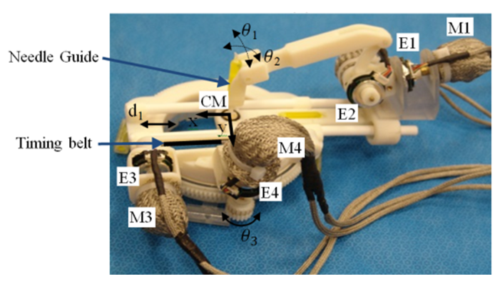
The purpose of this project is to further streamline the workflow for robotic-assisted MR-guided arthrography using a body-mounted robot introduced by Monfaredi et al. 1-2 and shown in Fig. 1. Using a commercial imaging coil can restrict the robot workspace and can interfere with the robot movements. Furthermore, the proximity of the robot to the coil can change coil tuning and compromise coil sensitivity. To address these issues, a single loop coil was created and embedded into the mounting adaptor of the robot.2. METHODS
2.1. Designing and Fabrication of the RF Coil
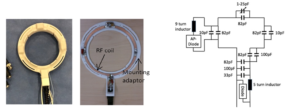
The custom-made coil was embedded as shown in Fig. 2(a). Figure 2(b) shows the electronic circuit of the receive coil. The coil was constructed with a conventional balun and incorporated both active and passive blocking. It was tuned to 63.8 MHz, the Larmor frequency of a 1.5T MR scanner. Tuning and matching were performed with the robot in place to maximize coil sensitivity. A 16-channel preamplifier box tuned to 63.8 MHz was also constructed. The box also incorporates coil identification circuitry and biasing circuitry to control active coil blocking.
2.2. Experimental Setup
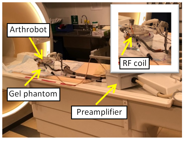
We conducted two studies to test the coil: 1) SNR study to quantitatively evaluate coil sensitivity, and 2) targeting study on phantom using MR images acquired by the new coil for fiducial segmentation and robot registration. The targeting study was conducted on a 1.5 T Philips Ingenia scanner with a 20G MRI-compatible needle. The experimental setup is shown in Fig. 3. T1 weighted MR images were acquired. The line marker registration module with the open source software 3D Slicer was used for segmentation of four fiducials embedded in the base of the robot. Six targeting procedures were conducted. After each targeting attempt, a confirmation MR image was acquired to measure the error.
3.RESULTS
3.1. RF Coil Evaluation
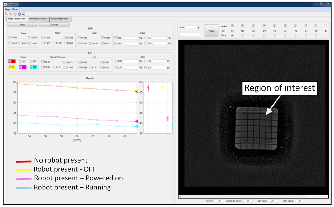
The phantom and software developed by Stoianovici et al. 3 was used for an SNR study. T1-weighted images (2D Spin Echo, FA=90, TE=20 ms, and TR= 500 ms) of the phantom in isolation were acquired using the custom-made coil. Then, new sets of MR images were acquired, in the presence of the robot, when the robot was: 1) Off, 2) Powered on, and 3) Running. As shown in Fig. 4, SNR dropped by 32% for the T1-weighted imaging sequence, when the robot was powered and running, compared to the baseline (no robot present). The presence of an unpowered robot had no impact on SNR.
3.2. Targeting Study
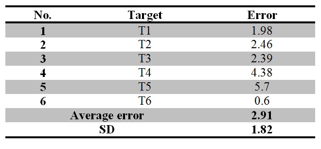
To measure the targeting error, multiple points were selected manually along the needle in 3D Slicer. A straight line was fitted to these points using Matlab. The Euclidean distance between the resulting estimated line and the center of the target (plastic spheres inside the ballistic gel phantom) was calculated. The results of the 6 targeting tests are reported in Table 1. The average targeting error was 2.91 mm with a standard deviation of 1.82 mm.
4. DISCUSSION
The integrated coil and body-mounted robot enables a new approach to streamline MRI-guided arthroscopy by making coil management easier. This coil provides sufficient spatial coverage and sensitivity to localize anatomical points of interest and registration fiducials within the working space of the robot. While a reduction in SNR was observed when the robot was powered on, this reduction did not influence the robot’s ability to target the plastic spheres in this phantom study.5. CONCLUSION
MRI time is expensive and streamlining the clinical workflow will be important in enabling future MRI interventions. In this paper we discussed the development of a single loop imaging coil for our patient-mounted MRI-compatible robot for MR image-guided interventions. This coil eliminates the requirement for additional imaging coils during registration and needle placement procedures which usually restrict the robot motion and needle placement. SNR experiments showed no significant noise in a phantom study when the robot was powered off. Targeting study showed promising results based on minimum required targeting accuracy in needle-based interventions.Acknowledgements
No acknowledgement found.References
[1] R. Monfaredi, R. Seifabadi, I. Iordachita, R. Sze, N.M. Safdar, K. Sharma, S. Fricke, A. Krieger, and K. Cleary, "A prototype body-mounted MRI-compatible robot for needle guidance in shoulder arthrography," in Proc. IEEE RAS & EMBS Int. Conf. Biomedical Robotics and Biomechatronics (BioRob), Sao Paulo, Brazil, 2014, pp. 40-45.
[2] R Monfaredi, E Wilson, R Sze, K Sharma, B Azizi, I Iordachita, K Cleary, "Shoulder-Mounted Robot for MRI-guided arthrography: Accuracy and mounting study," in 37th Annual International Conference of the IEEE Engineering in Medicine and Biology Society , Milan, Italy, 2015, pp. 3643-3646.
[3] D. Stoianovici, C. Jun, S. Lim, P. Li, D. Petrisor, S. Fricke, K. Sharma, K. Cleary, "Multi-Imager Compatible, MR Safe, Remote Center of Motion Needle-Guide Robot," IEEE Trans Biomed Eng., vol. 65, no. 1, pp. 165-177, 2018.
Figures