3843
MRI artifact simulation for clinically relevant MRI sequences for guidance of prostate HDR brachytherapy1Department of Radiotherapy, University Medical Center Utrecht, Utrecht, Netherlands, 2Image Sciences Institute, University Medical Center Utrecht, Utrecht, Netherlands
Synopsis
Object localization by MRI artifact simulation and template matching is valuable for MRI-guided HDR brachytherapy. Simulations of the artifacts induced by an HDR brachytherapy source and titanium needle were implemented for four types of MRI sequences: spoiled gradient echo, spin echo, bSSFP and bSSFP-SPAIR. The simulated artifacts were compared to MR images acquired in a phantom study and applied for object localization. High correspondences between the simulations and MR images were found as well as only slight variations between the obtained object positions for all applied sequences. This enables object localization for clinically relevant MRI sequences which allow anatomy visualization.
INTRODUCTION
During prostate high-dose-rate (HDR) brachytherapy, a high-intensity radiation source (Ir-192) is inserted temporarily into catheters implanted into/close to a tumor, to irradiate internally. MRI is an important imaging modality to guide the treatment, and could be employed for tracking of an HDR brachytherapy source or needle by exploiting the MRI artifacts induced by the object. The MRI artifacts can be simulated and applied in template matching for localization of the object1. This has been performed for spoiled gradient echo sequences. However, these sequences provide no sufficient contrast between tissues. Here, the potential of clinically relevant MRI sequences for object localization was investigated. The purpose was to simulate the MRI artifacts for several clinically relevant MRI sequences for HDR brachytherapy to facilitate tracking/localization of brachytherapy devices (HDR source/needle), which simultaneously allow visualization of the anatomy. Simulations were implemented for a spoiled gradient echo sequence, a spin echo sequence, a balanced steady-state free precession (bSSFP) sequence and a bSSFP sequence with spectral attenuated inversion recovery (SPAIR) fat suppression.METHODS
Simulations
Simulation of the artifact for a spoiled gradient echo sequence was performed as described in[1], and implemented in Matlab. The simulations involve a forward calculation of the magnetic field perturbation2, ∆B0, based on the susceptibility distribution, and inclusion of the MRI signal equation (corresponding with the sequence) and k-space sampling. The signal equation of a spoiled gradient echo sequence for each kx (with readout direction along x) was defined as1,3:
$$S(k_x,y,z)=\sum_{j=1}^{N_x}\rho(x_j,y,z){\cdot}e^{i2\pi\gamma{\Delta}B_0(x_j,y,z)\cdot(TE+n{\Delta}t)}{\cdot}e^{-i2{\pi}k_xx_j},$$
where $$$k_x={\gamma}G_Rn{\Delta}t$$$, γ the gyromagnetic ratio, GR the readout gradient strength ($$$G_R=\frac{1}{{\gamma}FOV_x{\Delta}t}$$$), n=-Nx/2…Nx/2-1 with Nx the number of spin isochromats along x and ∆t the sampling interval. This equation was implemented, and the other sequences were simulated by adapting the MRI signal equation. For a spin echo sequence, the spatial dephasing effect ($$$e^{i2\pi{\Delta}B_0(x_j,y,z){\cdot}TE}$$$) was excluded because of the 180° refocusing pulse:
$$S_{spin\:echo}(k_x,y,z)=\sum_{j=1}^{N_x}\rho(x_j,y,z){\cdot}e^{i2\pi{\Delta}B_0(x_j,y,z)n{\Delta}t}{\cdot}e^{-i2{\pi}k_xx_j}.$$
For bSSFP, the spin distribution, ρ(x,y,z), was replaced by the steady-state signal equation of a bSSFP sequence, Mxy(x,y,z):
$$S_{bSSFP}(k_x,y,z)=\sum_{j=1}^{N_x}M_{xy}(x_j,y,z){\cdot}e^{i2\pi{\Delta}B_0(x_j,y,z)\cdot(TE+n{\Delta}t)}{\cdot}e^{-i2{\pi}k_xx_j},$$
where Mxy is defined as4:
$$M_{xy}(x,y,z)=M_x(x,y,z)+iM(x,y,z),$$
and Mxy is decomposed in the x and y components:
$$M_x(x,y,z)=M_0(1-E_1)\frac{\sin\alpha(1-E_2\cos\beta}{d},$$
$$M_y(x,y,z)=M_0(1-E_1)\frac{E_2\sin\alpha\cos\beta}{d},$$
where the following definitions hold:
$$E_1=e^{-TR/T_1},$$
$$E_2=e^{-TR/T_2},$$
$$d=(1-E_1\cos\alpha)(1-E_2\cos\beta)-E_2(E_1-\cos\alpha)(E_2-\cos\beta),$$
with M0 the equilibrium magnetization, α is the flip angle, β is the resonance offset angle and TR is the repetition time. The impact of ∆B0 is reflected in the resonance offset angle:
$$\beta=2\pi({\delta}_{CS}+\gamma{\Delta}B_0(x,y,z)){\cdot}TR-\phi_{RF},$$
where 𝛿𝐶𝑆 is the chemical shift and 𝜙𝑅𝐹 the RF phase increment in successive TRs (in this study: $$$\phi_{RF}=\pi$$$). Lastly, for SPAIR, the spins at a frequency of the SPAIR pulse were set to 0 (in this study: between -1.8 and -5.2 ppm for a SPAIR pulse with a frequency offset of 110 Hz).
MRI acquisition
The object, a non-active Ir Flexisource (Elekta) or a titanium needle (Ø1.9mm, Elekta), was positioned in the center of a doped water phantom. MR imaging was performed on a 1.5T MRI system (Ingenia, Philips). Two imaging approaches were distinguished: (I) fast 2D sequences for (real-time) tracking, and (II) clinically applied 3D/volumetric sequences for robust object localization and position verification. Four types of 2D MR sequences were applied (2 intersecting 2D slices): spoiled gradient echo, spin echo, bSSFP and bSSFP-SPAIR, see Table1a. Furthermore, the MRI sequences of the clinical prostate HDR brachytherapy scan protocol were applied: a 3D bSSFP-SPAIR sequence, a T2-weighted and a T1-weighted turbo spin echo sequence (both multi-slice 2D), see Table1b. Angles of 0° and 20° between source/needle and B0 were applied.
Post-processing
RESULTS AND DISCUSSION
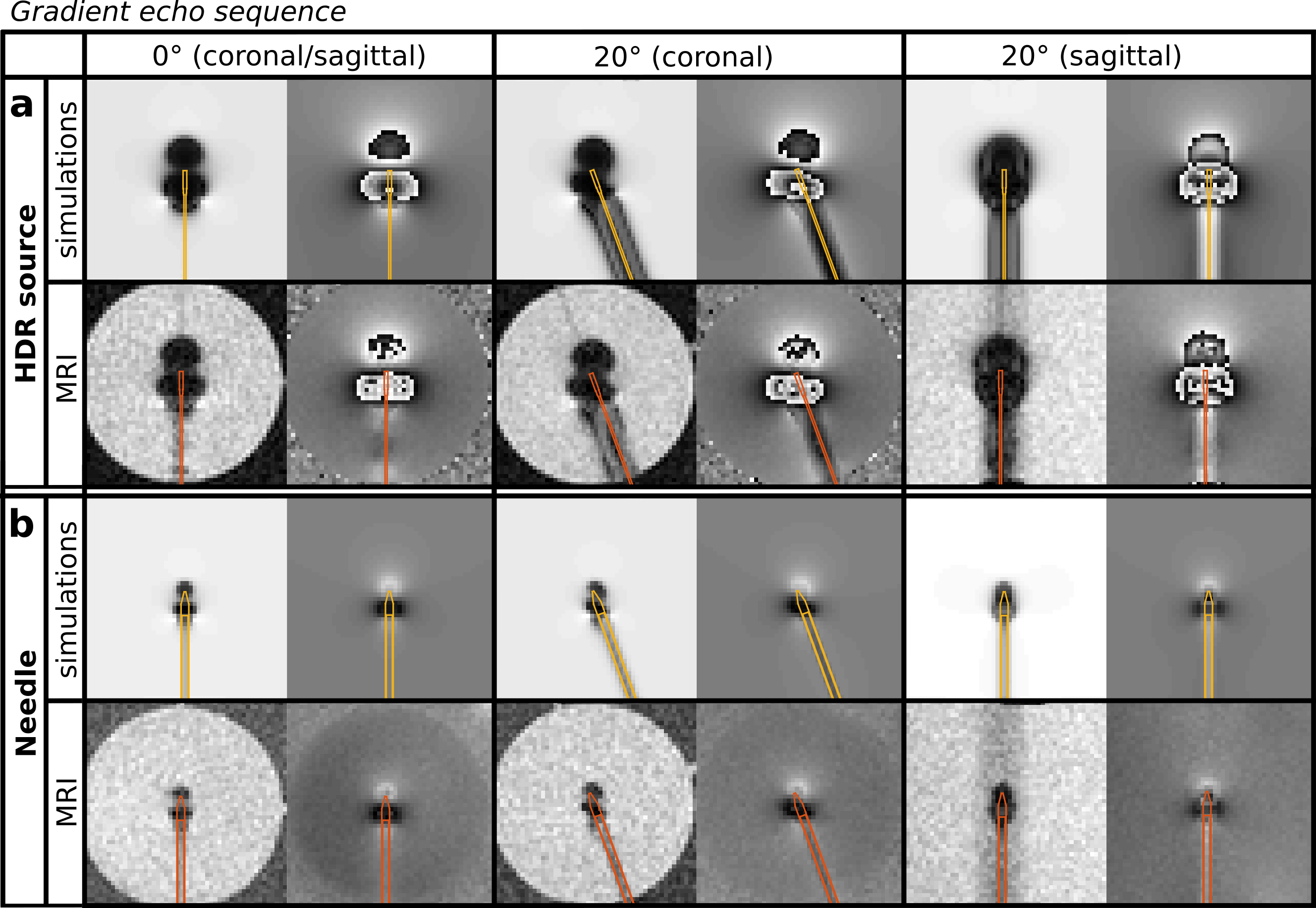
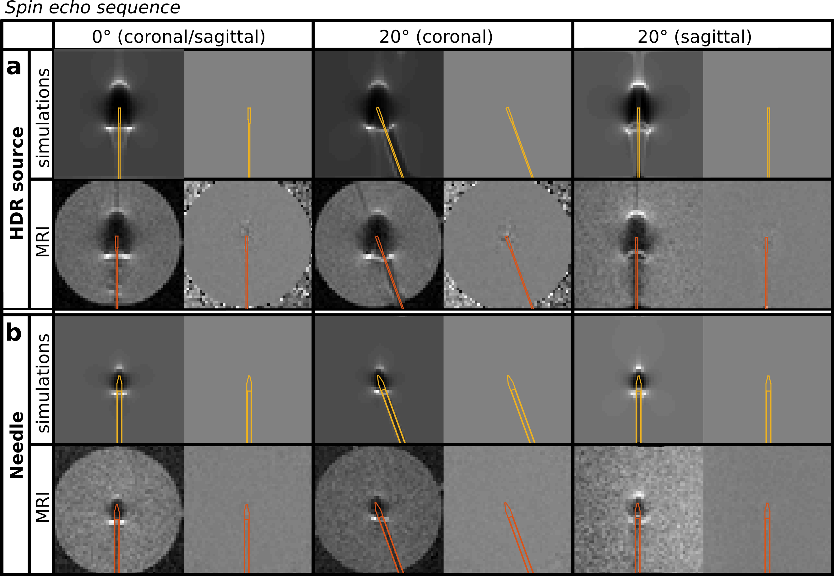
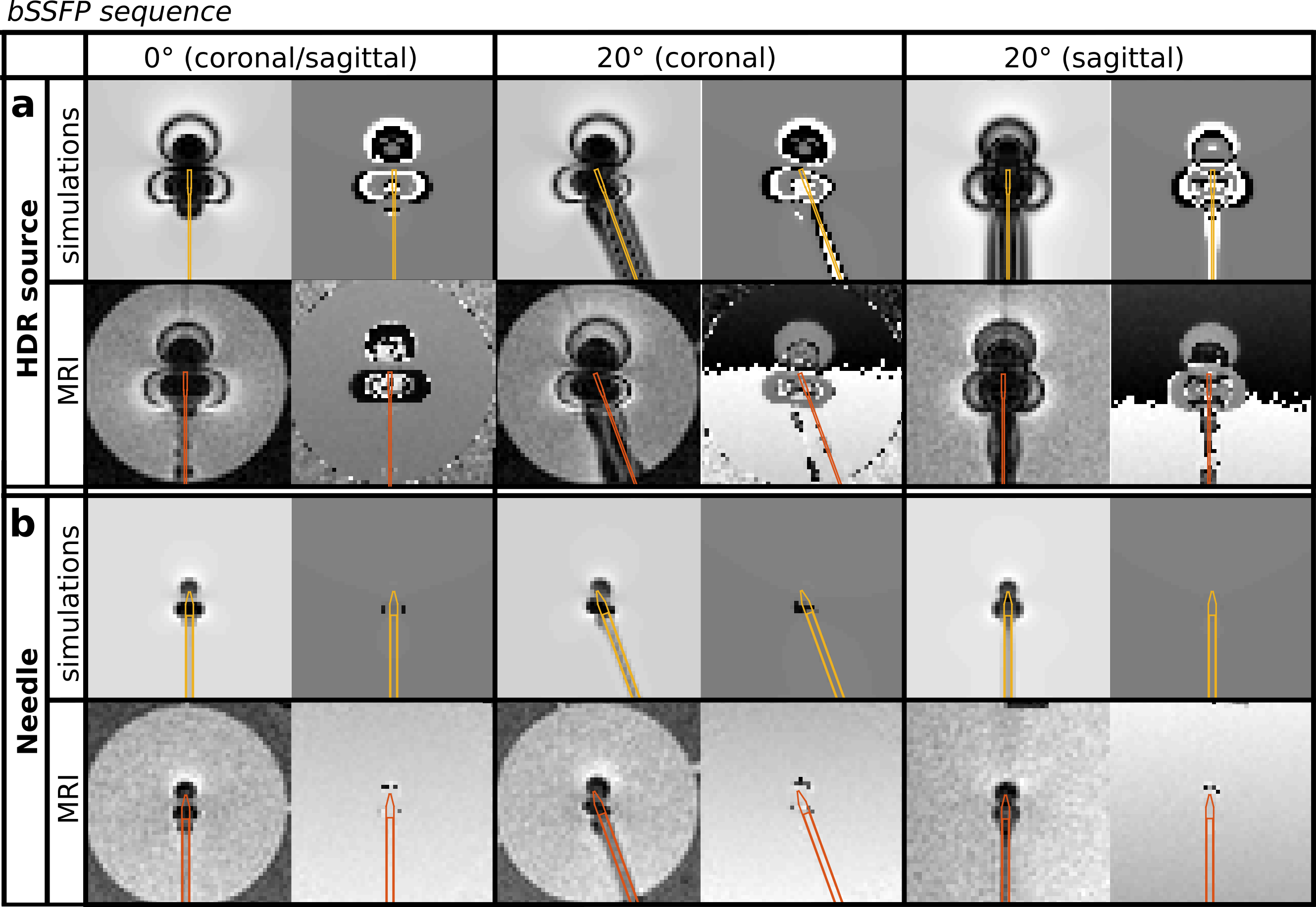
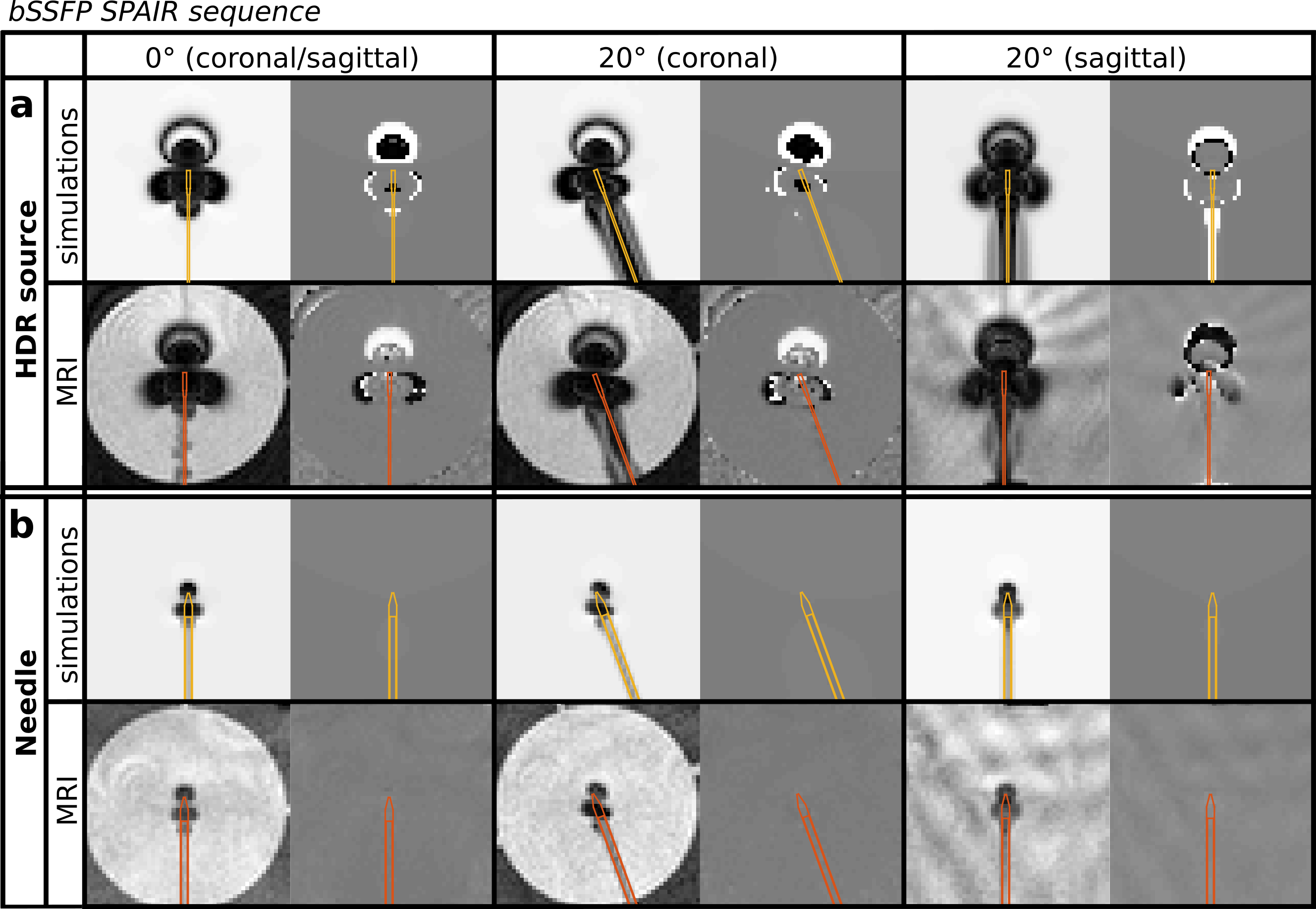
Figures 1, 2, 3 and 4 show the simulated and acquired MR images for the four applied 2D sequences: spoiled gradient echo, spin echo, bSSFP and bSSFP-SPAIR respectively (with the object positions overlaid). High correspondences between the simulated and acquired MRI artifacts were observed. The mean deviations (and range) from the average object position were 0.2(0.1-0.2) mm and 0.2(0.1-0.4) mm for the HDR source at 0° and 20° respectively, and 0.3(0.1-0.6) mm and 0.2(0.1-0.4) mm for the needle at 0° and 20° respectively. This proved that all applied MRI sequences were suitable for localization of the objects. CONCLUSION
This study has demonstrated the simulation of MRI artifacts induced by an HDR source/needle for four types of MRI sequences: gradient echo, spin echo, bSSFP and bSSFP-SPAIR. These simulations enable object localization using a phase correlation localization algorithm for clinically relevant MRI sequences, which simultaneously allow visualization of the anatomy.Acknowledgements
This research was funded by the Eurostars Programme, ITEA3, project name: System of Real-Time Systems (SoRTS), project number: 12026.References
1. E. Beld, M.A. Moerland, F Zijlstra, M.A. Viergever, J.J.W. Lagendijk and P.R. Seevinck MR-based source localization for MR-guided HDR brachytherapy Phys. Med. Biol. 2018; 63:085002
2. J.G. Bouwman and C.J.G. Bakker Alias subtraction more efficient than conventional zero-padding in the Fourier-based calculation of the susceptibility induced perturbation of the magnetic field in MR Magn. Reson. Med. 2018; 68:621-630
3. F. Zijlstra, J.G. Bouwman, I Braskute, M.A. Viergever and P.R. Seevinck Fast Fourier-based simulation of off-resonance artifacts in steady-state gradient echo MRI applied to metal object localization Magn. Reson. Med. 2017; 78:2035-2041
4. M.L. Lauzon and R. Frayne Analytical characterization of RF phase-cycled balanced steady-state free procession Concepts Magn. Reson. 2017; 34A:133-143
5. C.D. Kuglin and D.C. Hines The phase correlation image alignment method Proc. IEEE Int. Conf. Cybernet. Soc. 1975; 163-165
Figures
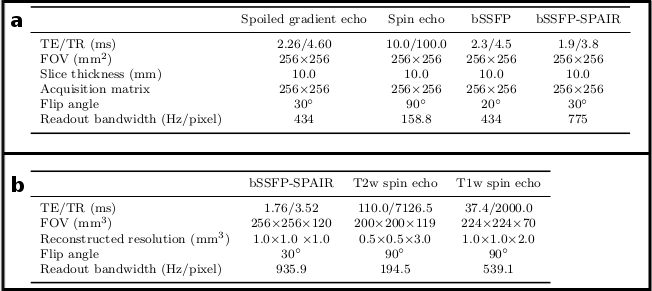
Table 1a. The scan parameters of the spoiled gradient echo sequence, the spin echo sequence, the bSSFP sequence and the bSSFP-SPAIR sequence that were applied (all 2D).
Table 1b. The scan parameters of the 3D bSSFP sequence, the multi-slice 2D T2-weighted (T2w) spin echo sequence and the multi-slice 2D T1-weighted (T1w) spin echo sequence that were applied (as provided in the current clinical scan protocol of prostate HDR brachytherapy).