3841
Modeling of Active Shimming of Metallic Needles for Interventional MRI1Department of Radiology, Vanderbilt University Medical Center, Nashville, TN, United States
Synopsis
Needle artifacts caused by large magnetic susceptibility differences between metallic needles and stylets and the surrounding tissue are a persistent problem in interventional MRI. In this abstract, we present the concept, design and modeling results of a active shim system for needles inspired from degaussing coils used in naval vessels. Field disturbance induced by a Titanium needle at 3 Tesla is modeled and an active orthogonal shim coil insert design is presented to demonstrate shimming of the field variation around the needle. This work lays the foundation for designing full generalized active shim systems for Interventional MRI probes.
INTRODUCTION
Needle artifacts have long presented a challenge in Interventional MRI (IMRI)1-3. The large difference in magnetic susceptibility between needles and the surrounding tissue induces significant field perturbations that result in a variety of artifacts around the needle. These artifacts obscure targets for example in biopsies4 and prevent accurate image based monitoring in therapeutic applications5. The purpose of this work is to therefore introduce a solution for this problem by developing active shim coils to correct the field disturbance caused by the needle. In this abstract, we present conceptual details of the method and initial results of the design and modeling of the shim coils.METHODS
The proposed solution is inspired from degaussing coil technology used in ships and submarines for defense against magnetic field sensitive sea mines as well as recent work in local shim coils for brain MRI6-9. Similar to a ship’s degaussing coil structure, a shim insert with DC coils is proposed that will produce the necessary corrective field outside the needle.
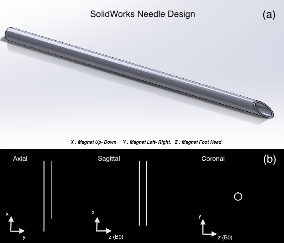
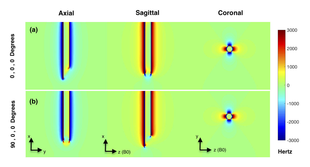
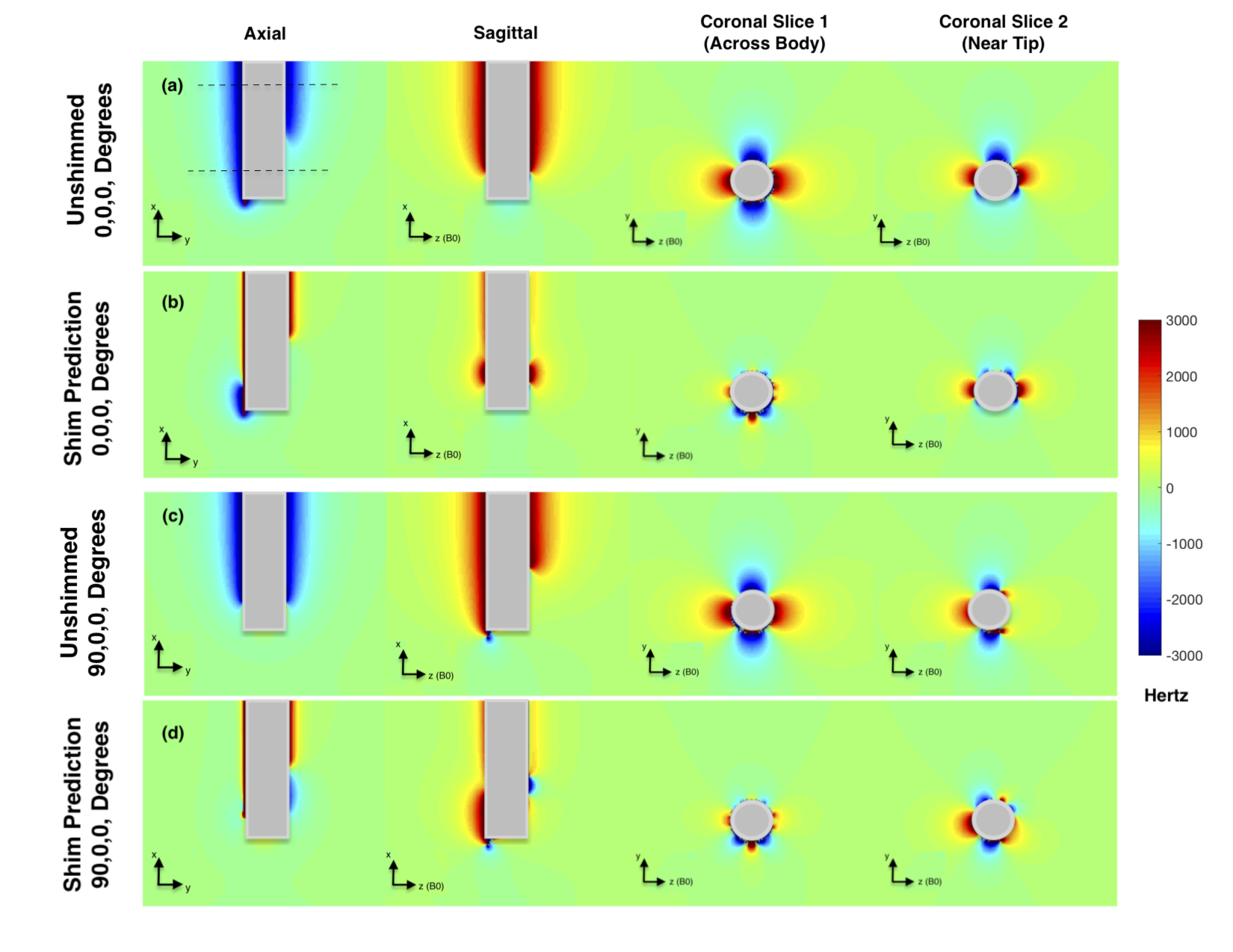
Needle Design and Field Modeling : We modeled the shimming of a 10 Gauge (3.4/2.7 mm OD/ID) Titanium needle ( Volume Susceptibility : 𝟀 = 182*10-6 ) in a surrounding medium of Water (𝟀 = -9.05*10-6 )10. A 100 mm hollow needle was designed in SolidWorks (Dassault Systemes, MA, USA) with a 30o single sided bevel at the tip. The design was exported as an .STL file into MATLAB ( Mathworks, MA, USA) and voxelized to yield a 3D grid of points defining the needle in space (Figure 1). The voxel resolution was set to 0.1 mm. A sub-grid of 40 mm3 ( 4003 voxels) was used for modeling the field from the top 3 cm of the needle. The field was modeled for two orientations with needle orientated perpendicular to the B0 field, along the magnet’s up-down (X) axis. The field distortion was computed using Fourier-analysis based field modeling at 3 Tesla11,12.
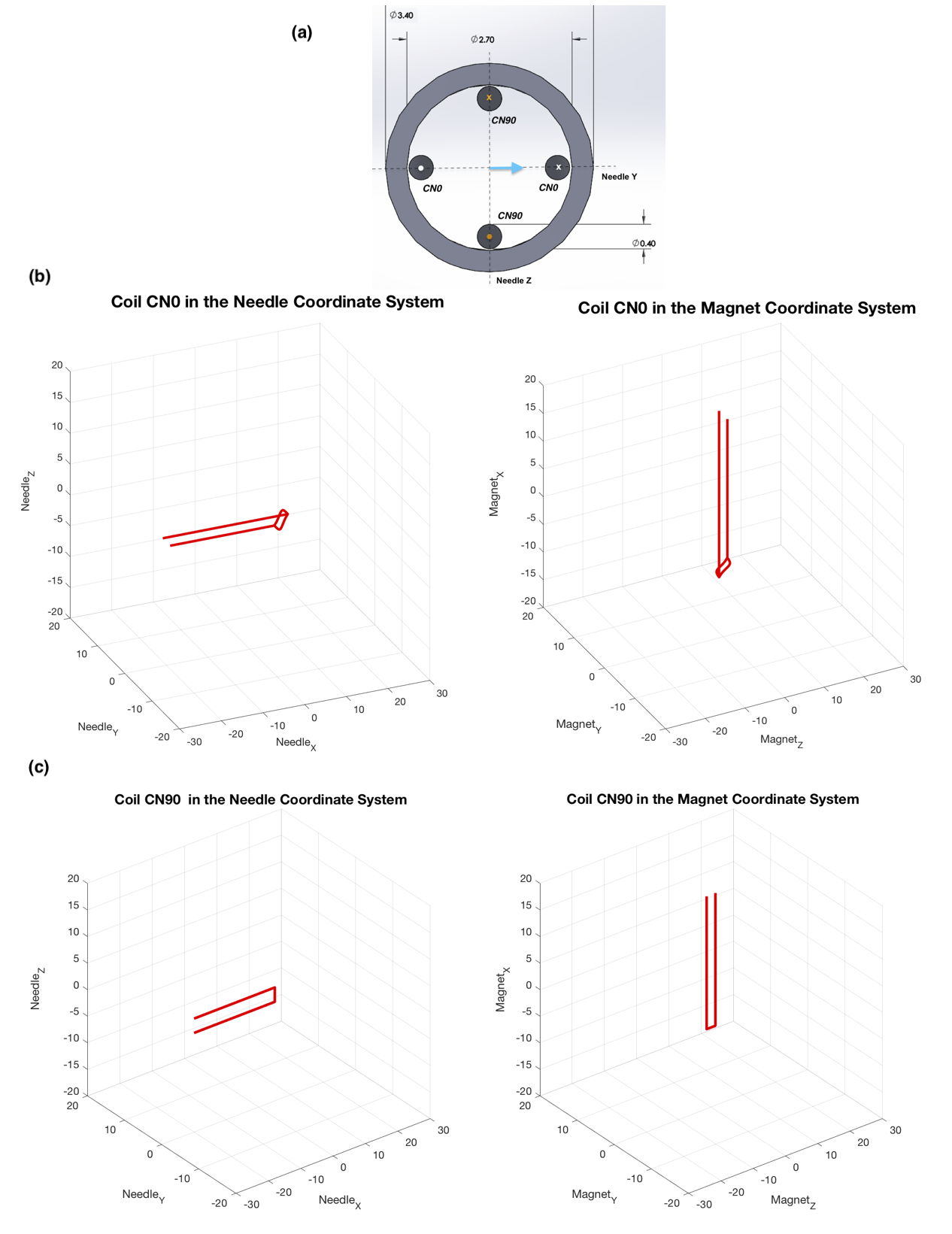
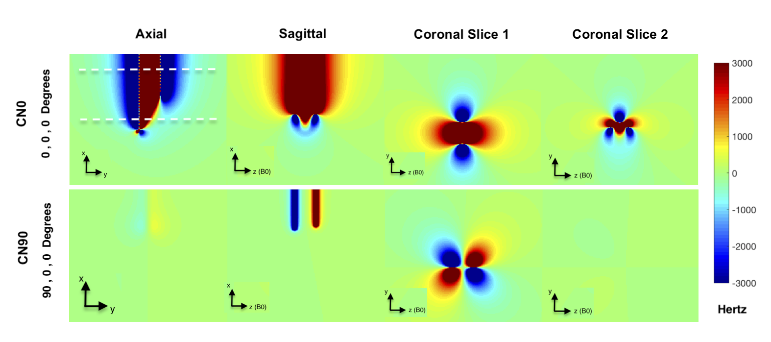
Shim Coil Design and Modeling : Two shim coils with 26G (0.4 mm OD) wire were designed in the needle’s coordinate system ( XN : Along needle length, YN , ZN : along radial directions) with normals along ZN (CN0) and YN (CN90). CN0 was designed with an angled split loop at its tip (with half the current in each arc) that followed the needle tip bevel. Coil geometry was transformed into the scanner’s coordinate frame assuming a (0,0,0) degree orientation along the magnet’s X axis. (Figure 3). The field from each coil in the 4003 target grid was then estimated by using an implementation of Biot-Savart’s field induction formula7-9, with a current path resolution element of 0.4 mm. A current of 1 Amp was used to calculate the unit Bz(r) field for both shim coils.
Field Shimming : The field produced by the two shim coils were used to shim the needle induced field by multilinear least squares fitting in Matlab with a mask defined to exclude voxels within the needle. The currents were constrained to 600 mAmperes in each coil.
RESULTS
Figure 2 shows the modeled ΔB0 of the needle for two orientations. The familiar dipolar pattern is observed that varies with needle orientation. Figure 4 shows the fields produced by the two coils for 1 Amp. The field variation is similar to that induced by the needle, which indicates the feasibility of shimming. Note that while the CN0 field matches the needle ΔB0, the CN90 field has a phase offset. As the needle is rotated about the X axis, the two coils therefore perform in a phased manner. Figure 5 shows the results of shimming. There is good correction of the ΔB0 induced by the needle in both orientations. The standard deviation of the field outside the needle was reduced from 334.6 Hz to 178.7 Hz for orientation 1 with currents of 510 mA and 2 mA and from 335 Hz to 192 Hz for orientation 2 with currents of 0 mA and 494 mA for CN0 and CN90 respectively. A small uncompensated field remained at the tip of the needle where the coils did not reach.DISCUSSION
The results demonstrate the feasibility of shimming a needle with active shim coils. Generalized coil paths can be designed to provide robust shimming for all needle orientations, including ones designed using stream function methods13. The wire sizes and current constraints will clearly scale with needle size. For the 26G wire used here, the current capacity is ~505 mA assuming a coefficient of 500 circular-mils/Amp14. Our future work will include all these considerations in the design and eventual fabrication of such needles.Acknowledgements
This work was supported by NIBIB 1R21EB025258. I would like to thank Dr Megan Poorman and Dr William A Grissom for advice and discussions on field modeling.References
1. Weiss CR, Nour SG, Lewin JS. MR-guided biopsy: a review of current techniques and applications. J Magn Reson Imaging. 2008 Feb;27(2):311-25. PMID: 18219685 doi: 10.1002/jmri.21270. Nour SG,
2. Lewin JS Percutaneous biopsy from blinded to MR guided: an update on current techniques and applications. Magn Reson Imaging Clin N Am. 2005 Aug;13(3):441-64. PMID: 16084412 DOI: 10.1016/j.mric.2005.04.009
3. Butts K, Pauly JM, Daniel BL, Kee S, Norbash AM.Management of biopsy needle artifacts: techniques for RF-refocused MRI. J Magn Reson Imaging. 1999 Apr;9(4):586-95. PMID: 10232519
4. Kuhl CK, Morakkabati N, Leutner CC, Schmiedel A, Wardelmann E, Schild HH.MR imaging--guided large-core (14-gauge) needle biopsy of small lesions visible at breast MR imaging alone. Radiology. 2001 Jul;220(1):31-9.PMID: 11425969 DOI: 10.1148/radiology.220.1.r01jl0731
5. Xinyang Liu; Kemal Tuncali; William M. Wells; Gary P. Zientara. Automatic probe artifact detection in MRI-guided cryoablation. Conference: Proc. SPIE 8671, Medical Imaging 2013: Image-Guided Procedures, Robotic Interventions, and Modeling, 86712E DOI: 10.1117/12.2008530
6. Juchem C, Nixon TW, McIntyre S, Rothman DL, de Graaf RA.Magnetic field homogenization of the human prefrontal cortex with a set of localized electrical coils.Magn Reson Med. 2010 Jan;63(1):171-80. PMID: 19918909 PMCID: PMC3046864 DOI: 10.1002/mrm.22164
7. Stockmann JP, Witzel T, Keil B, Polimeni JR, Mareyam A, LaPierre C, Setsompop K, Wald LL.A 32-channel combined RF and B0 shim array for 3T brain imaging.Magn Reson Med. 2016 Jan;75(1):441-51. PMID: 25689977 PMCID: PMC4771493 DOI: 10.1002/mrm.25587
8. Truong TK, Darnell D, Song AW.Integrated RF/shim coil array for parallel reception and localized B0 shimming in the human brain.Neuroimage. 2014 Dec;103:235-40. PMID: 25270602 PMCID: PMC4312247 DOI: 10.1016/j.neuroimage.2014.09.052
9. Holmes JJ : Modeling a ship’s ferromagnetic signatures. ISBN 978159829249
10. Schenck JF The role of magnetic susceptibility in magnetic resonance imaging: MRI magnetic compatibility of the first and second kinds.Med Phys. 1996 Jun;23(6):815-50.
11. Salomir, R., de Senneville, B. D. and Moonen, C. T. (2003), A fast calculation method for magnetic field inhomogeneity due to an arbitrary distribution of bulk susceptibility. Concepts Magn. Reson., 19B: 26–34. doi:10.1002/cmr.b.10083
12. Marques, J.P. and Bowtell, R. (2005), Application of a Fourier-based method for rapid calculation of field inhomogeneity due to spatial variation of magnetic susceptibility. Concepts Magn. Reson., 25B: 65–78. doi:10.1002/cmr.b.20034
13. M. Poole, D. Green and R. Bowtell. Shoulder-Slotted Insertable Gradient and Shim Coil Set. Proceedings of the International Society for Magnetic Resonance in Medicine, 16, 1165, (2008).
14. Colonel Wm. T. McLyman. Transformer and Inductor Design Handbook, Third Edition (Electrical and Computer Engineering) ISBN 10: 0824753933 ISBN 13: 9780824753931 Publisher: CRC Press, 2004
Figures