3830
Performance of an aerosol jet-deposited wireless resonant marker: in vitro temperature measurements and in vivo visualization1Radiology and Biomedical Imaging, University of California, San Francisco, San Francisco, CA, United States, 2Quest Integrated, Kent, WA, United States, 3Graduate Program in Bioengineering, UC Berkeley-UCSF, Berkeley, CA, United States, 4Bioengineering and Therapeutic Sciences, University of California, Berkeley, Berkeley, CA, United States, 5Radiology, Stanford University, Stanford, CA, United States, 6Electrical Engineering, Stanford University, Stanford, CA, United States
Synopsis
Endovascular catheter-based procedures under MRI can be challenging as standard fabrication methods for markers are rigid and bulky, and new microfabrication methods need more analysis on their tracking characteristics. We analyzed a wireless resonant circuit tracking marker that was printed using aerosol jet deposition on a polymer catheter. In a phantom, we acquired bSSFP sequences and a B1+ map, and measured temperature using probes and MR thermometry. In vivo, in the carotid arteries, we acquired GRE sequences and a B1+ map. The marker demonstrated good signal, with minimal temperature increases, suggesting that these markers have good tracking characteristics.
Introduction
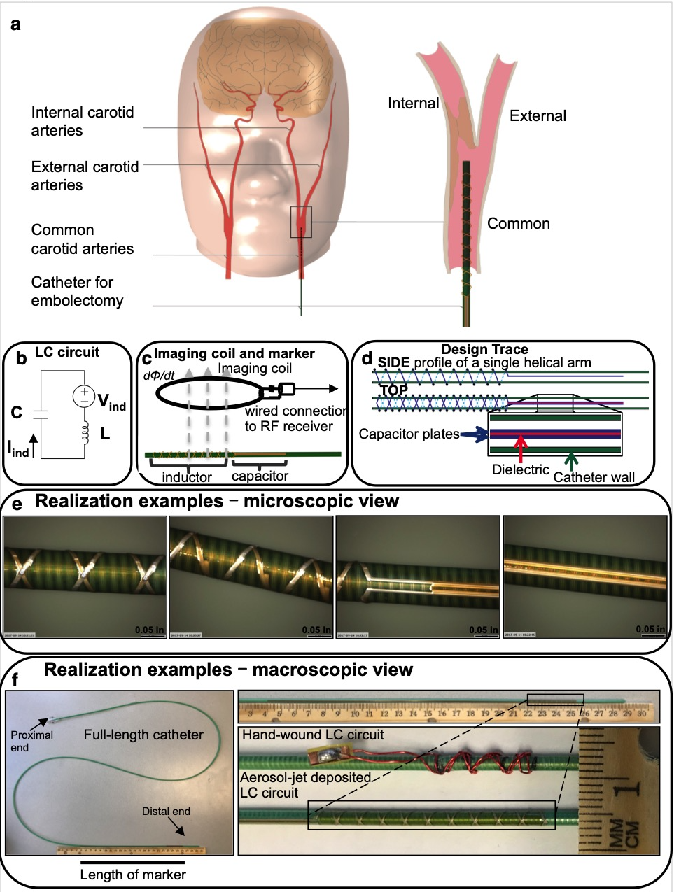
Endovascular embolectomy under X-ray guidance is an effective treatment for patients suffering an acute ischemic stroke (Fig. 1a); however, fewer than 10% of patients receive such treatments due to the limited time window1. MRI could extend this window since diffusion weighted imaging (DWI), in combination with perfusion imaging, is the gold standard in determining if brain tissue is still viable. Interventional MRI has not been adapted, and there are a lack of tools. One method to track markers uses a wireless RLC circuit,2 (Fig. 1b) which inductively couples with the magnetic flux from the RF, resulting in induced current, and a local magnetic field3 (Fig. 1c). Recent work implemented an inductor geometry of a double helix4,5 (Fig. 1d), using aerosol jet deposition6 (Fig. 1e, f), a new additive manufacturing process7; however, characterization of heating and in vivo performance is limited. We demonstrate analysis of the tracking characteristics of an aerosol jet-deposited resonant marker by measuring temperature in vitro, and testing the markers in a preclinical embolectomy scenario in vivo.Methods
In vitro experiment
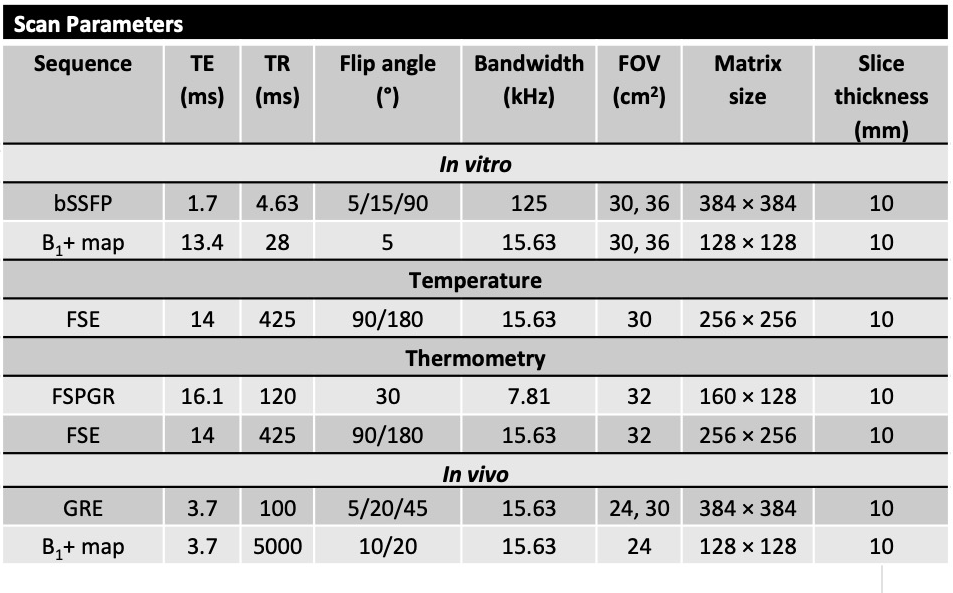
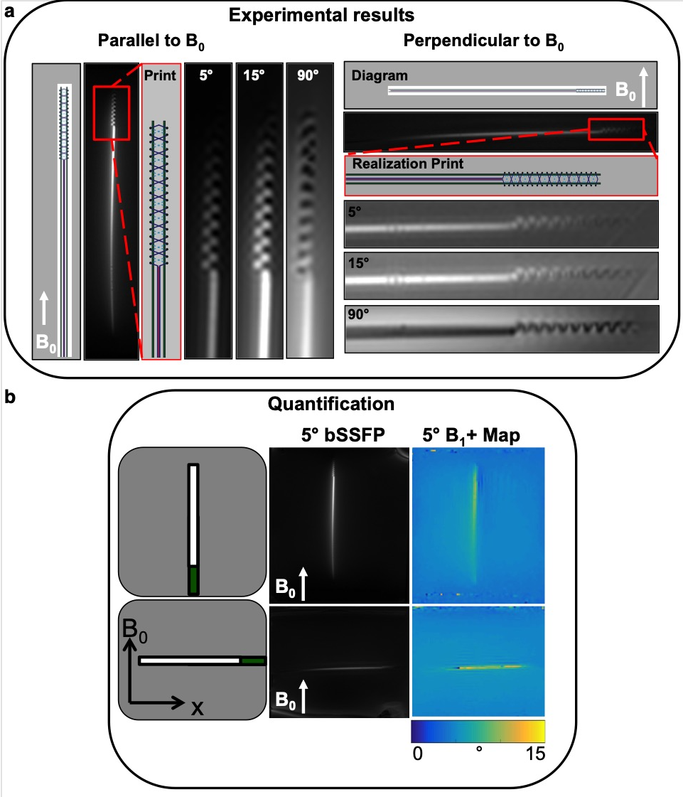
An aerosol jet-deposited marker catheter6 was placed in a rectangular water phantom doped with CuSO4 and the phantom was oriented either parallel or perpendicular to B0. Images were acquired in both orientations at 3.0T (Discovery MR 750w, GE Healthcare) using an 8-channel cardiac coil. A balanced steady state free precession (bSSFP) sequence, and a 5° Bloch-Siegert B1+ map8,9 were acquired (Table 1). An ROI was manually drawn around the entire marker to measure the mean signal, and then the ratio with the nearby background water signal was calculated for the relative amplification factor. Image processing was performed in MATLAB 2016a (MathWorks Inc., Natick, MA).
Temperature measurements
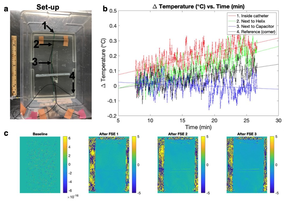
A Hydroxyethyl cellulose gel was prepared10, and four temperature probes (Luxtron, LumaSense Technologies, Inc. Santa Clara, CA) were placed in the gel (Fig. 3a). Temperature was recorded every second during a fast spin echo (FSE) sequence, as well as two minutes before and after the scan, for a total scan time of 15:02 min (Table 1). The baseline temperature of each probe at room temperature was subtracted for comparison. We then acquired a set of MR thermometry images in an oblique scan plan, parallel to the catheter (FSPGR, Tacq = 16 sec), interleaved with the periods of FSE acquisition with the number of averages of 1, 2, and 3 (Table 1) for a total scan time of 4:37 min. Temperature maps were generated offline with proton resonance frequency shift (PRF) technique.
In vivo experiment
The study protocol was approved by the university’s committee. A catheter was placed into each common carotid artery of a single swine (43.2 kg, female), using a 30 × 30 cm2 flat panel C-arm X-ray system guidance (Cios Alpha, Siemens Healthineers, Munich, Germany). A gradient recalled echo (GRE) sequence was acquired for visualization, and a 5° B1+ map using the double angle method11 (Table 1), with the same coil. An ROI was manually drawn around the entire marker to measure mean signal, and the relative amplification factor was calculated.
Results
In vitro results
The low flip angle bSSFP sequences (5° and 15°) show the signal amplification of the markers relative to the background signal, in comparison with the high flip angle (90°) sequence (Fig. 2a). For the 5° B1+ map, the relative amplification factor measured 1.63 in the parallel orientation, and 1.77 in the perpendicular orientation (Fig. 2b).
Temperature results
No appreciable heating was measured by the temperature probes (Fig. 3b). MR thermometry images confirmed this by demonstrating no detectable heating (Fig. 3c).
In vivo results
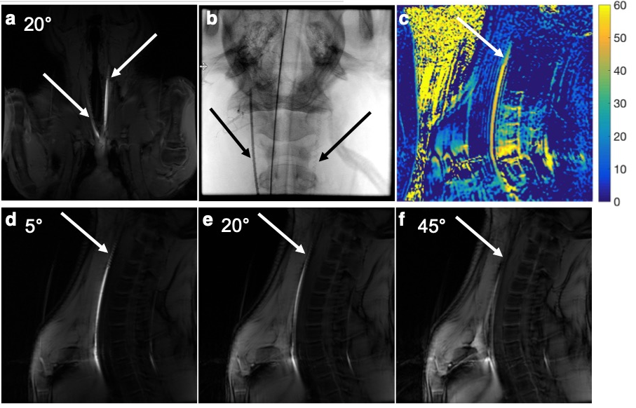
The coronal GRE sequence shows especially good signal and contrast for the catheter on the left side (Fig. 4a), and the two catheter placements can be seen on X-ray (Fig. 4b). The 10° B1+ map had an amplification factor of 5.3 (Fig. 4c). Using a lower flip angle of 5° demonstrates the low background signal, and the signal amplification of the marker (Fig. 4d). As the flip angle increases to 20°, there is more signal in the surrounding tissue, and the contrast decreases (Fig. 4e). With a higher flip angle of 45°, there is over-flipping of the marker signal, causing a decreased signal, while the background tissue signal increases (Fig. 4f).
Discussion
B1+ mapping, imaging, and temperature measurement experiments demonstrated that the wireless resonant circuit showed sufficient local signal amplification, while demonstrating no appreciable heating. We demonstrated good tracking characteristics of a complete LC circuit micro-fabricated using aerosol deposition, both in vitro and in vivo at 3T, allowing for a low profile guide catheter that can be tracked under MRI for endovascular neurointerventional applications.Acknowledgements
The authors gratefully acknowledge Andrew Chu and Dave Barry at Penumbra, Inc., for in-kind provision of catheters, Steven Conolly, PhD and Lucas Carvajal for engineering discussions, Labonny Biswas, PhD and Graham Wright, PhD for discussions about real-time imaging, and Jay F. Yu, Galen Reed, PhD, and R. Reeve Ingle, PhD for assistance with RTHawk. Funding supported included NIH grants UL1 TR001872, R01 EB012031, R21 EB020283, TL1 TR001871, T32 GM007618.References
1. Wintermark, M. et al. Imaging recommendations for acute stroke and transient ischemic attack patients: A joint statement by the American Society of Neuroradiology, the American College of Radiology and the Society of NeuroInterventional Surgery. JACR J. Am. Coll. Radiol.10,828–832 (2013).
2. Burl, M., Coutts, G. & Young, I. R. Tuned fiducial markers to identify body locations with minimal perturbation of tissue magnetization. Magn. Reson. Med. 36,491–3 (1996).
3. Kaiser, M. et al. Resonant marker design and fabrication techniques for device visualization during interventional magnetic resonance imaging. Biomed. Eng. / Biomed. Tech.60,(2015).
4. Thorne, B. R. H. et al. Micro Resonant Marker for Endovascular Catheter Tracking in Interventional MRI: In Vitro Imaging at 3T. in Proc. Intl. Soc. Mag. Reson. Med. 21,2327 (2014).
5. Thorne, B. R. H., Lillaney, P. V., Losey, A. & Hetts, S. Omnidirectional MRI catheter resonator and related systems, methods, and devices. WO2015164806A1 (2015).
6. Jordan, C. D. et al. An Aerosol-Deposited Wireless Resonant Marker for Catheter Tracking in Interventional MRI. in Proc. Intl. Soc. Mag. Reson. Med. 0649 (2018).
7. Paulsen, J. A., Renn, M., Christenson, K. & Plourde, R. Printing conformal electronics on 3D structures with aerosol jet technology. in FIIW 2012 - 2012 Future of Instrumentation International Workshop Proceedings47–50 (2012). doi:10.1109/FIIW.2012.6378343
8. Khalighi, M. M., Rutt, B. K. & Kerr, A. B. RF pulse optimization for Bloch-Siegert B+1 mapping. Magn. Reson. Med.68,857–862 (2012).
9. Sacolick, L. I., Wiesinger, F., Hancu, I. & Vogel, M. W. B1 mapping by Bloch-Siegert shift. Magn. Reson. Med.63,1315–1322 (2010).
10. ASTM F2182-11a, Standard Test Method for Measurement of Radio Frequency Induced Heating On or Near Passive Implants During Magnetic Resonance Imaging. ASTM International(2011). doi:10.1520/F2182-11A
11. Cunningham, C. H., Pauly, J. M. & Nayak, K. S. Saturated double-angle method for rapid B1+ mapping. Magn. Reson. Med.55,1326–1333 (2006).
Figures