3828
Power Considerations for Radiofrequency Applicator Concepts for Thermal Magnetic Resonance Interventions in the Brain at 297 MHz1Berlin Ultrahigh Field Facility (B.U.F.F.), Max-Delbrück-Center for Molecular Medicine in the Helmholtz Association, Berlin, Germany, 2MRI.TOOLS GmbH, Berlin, Germany, 3Clinic for Radiation Oncology, Charite University Medicine, Berlin, Germany, 4Biomedizinische Magnetresonanz, Physikalisch Technische Bundesanstalt, Berlin, Germany, 5Experimental and Clinical Research Center (ECRC), joint cooperation between the Charité Medical Faculty and the Max Delbrueck Center for Molecular Medicine in the Helmholtz Association, Berlin, Germany
Synopsis
There is a pressing need to implement Thermal MR therapies in the brain, particularly to sensitize treatment of aggressive cancers like glioblastoma multiforme. Given the high power transmission regime of Thermal MR therapies, it is crucial to understand the engineering constraints affecting RF power losses, since inaccurate estimates could compromise the efficiency and precision of the therapy. Here we conducted a thorough simulation of five RF applicator designs, using realistic loss estimates of material and electrical components, and considering antenna design, position and coupling. Results from simulated and patient-derived data underscore that clinical requirements must balance with practical engineering constraints.
Purpose
Localized thermal therapy has been convincingly demonstrated to potently sensitize chemo- and radiotherapy for several cancers1-4, and significantly improve patient survival5. Glioblastoma multiforme (GBM) is an especially attractive target for thermal therapy, given its aggressive nature and resistance to current treatment options6. Unfortunately, limitations of steering and energy deposition restrict the use of conventional thermal therapy approaches in the brain. Here, Thermal Magnetic Resonance (Thermal MR) has a unique potential to circumvent these limitations, and provide temperature manipulation, MR thermometry and imaging and in an integrated applicator. In the high power transmission regime of thermal MR therapies, it is crucial to have a comprehensive understanding of the engineering constraints that affect RF power losses, including material and electric component losses, as well as RF antenna design, positioning and coupling with respect to each other and the patient. The consequences of these challenges are too often under-appreciated – inaccurate estimates of the true RF power loss could compromise the efficiency and precision of Thermal MR therapy. To address this issue, the current study carefully investigated five RF applicator designs using realistic loss estimates, obtained with the power correlation matrix approach7. This work underscores the impact of real-world engineering constraints, and puts these into context with metrics used to quantify thermal therapy performance.Methods
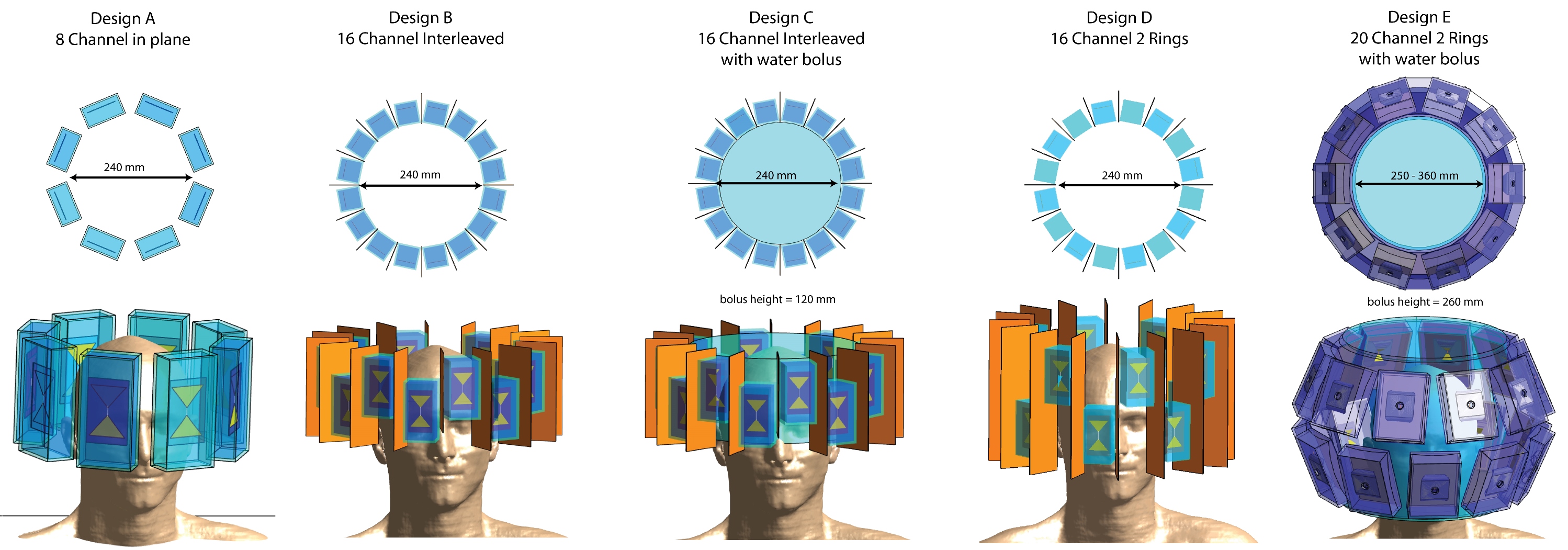
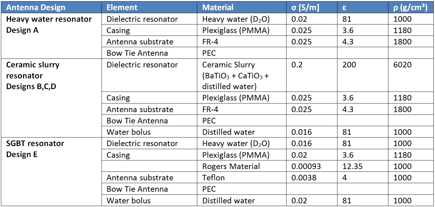
We examined the transmit performance of five thermal MR applicators at f=297MHz (Figure1, Table1, Design A-E). For the EMF simulations8 a patient model was approximated by superimposing the human voxel model Duke9 with a spherical tumor. A more clinically relevant voxel model was generated using radiation therapy (RT) treatment planning data of a GBM patient, with the target volume (TV) equal to the clinical target volume10. For designs A-D, a circuit co-simulation was performed, optimizing the values of two lossy capacitances for channel-wise matching and tuning. Channel-wise phase and amplitude optimization was performed11 to maximize power deposition in the TV under the constraint of SAR10g,max(healthy)≤40W/kg in healthy tissue10.
The hyperthermia treatment planning (HTP) performance was assessed considering, i) SAR10g,max(TV), ii) SAR10g,mean(TV) (i.e. power deposition), iii) SAR amplification factor SAF=SAR10g,mean(TV)/SAR10g,mean(healthy) (i.e. quality of the focusing) and iv) volume of the TV exposed to a higher SAR10g than SAR10g,max(healthy) (VSAR>Lim, i.e. TV coverage). Combining the measures for power deposition, focusing and coverage, we introduced the performance indicator PI=SAR10g,max(TV)·SAF·VSAR>Lim. The tumor coverage at 25% of maximum SAR TC25% was used as an established measure for hyperthermia treatment planning quality12,13. We calculated the power balance and compared the power delivered to the TV and the head, and the energy dissipated in the RF applicator.
Results & Discussion
Figure2 shows S-Matrices (all scattering parameters <-12.5dB) and HTP results for all designs applied to the small tumor. The HTP quality increased with each design iteration. For design D the increased longitudinal extent of the applicator causes high energy deposition in healthy tissue. Design E showed the best performance for PI, TC25% and required forward power (Table2).
Figure3 shows S-matrices (all scattering parameters <-13dB) and HTP results for the GBM patient data. The best HTP was achieved using design D. Given the large extent of the TV, the increased head coverage improved performance versus design B. The HTP performance of design E yielded highly focused energy deposition, leading to a small hotspot and poor coverage of the TV. Nonetheless it showed the best transmit efficiency. Conversely, Design D, which would have been chosen based on the quality of the HTP, required a forward power of >27kW. The high conductivity of the ceramic slurry induces high dielectric losses, leading to a transmit efficiency of <1% (PHead/PForward) with ~90% of the energy dissipated in the dielectric (PCoil/PForward, Designs B+D). The high forward power required for Designs B+D and the strong heating of the elements during thermal MR are challenging if not prohibitive for clinical applications. To address this shortcoming, the required forward power was offset by a factor of ~80 by adding a water bolus. This approach increased PHead/PForward to 15% (vs. 0.24%), while <8% of the forward power was dissipated in the bolus. With the PI of design C being equally high as for design B and a TC25% of still 75%, design C is better suited for practical realization. However, the efficiency gain of adding the water bolus (Design C) did not exceed the effect of better head coverage (Design D).
Conclusion
This work demonstrates that novel concepts for RF applicators tailored for thermal interventions in the human brain should balance clinical requirements with engineering constraints and practical considerations including proper power loss calculations.Acknowledgements
This work is supported by the German Federal Ministry of Education and Research (13GW0102) and an advanced ERC grant (DLV-743077).References
- Wust P, Hildebrandt B, Sreenivasa G, Rau B, Gellermann J, Riess H, Felix R, Schlag PM. Hyperthermia in combined treatment of cancer. Lancet Oncol 2002;3(8):487-497.
- Horsman MR, Overgaard J. Hyperthermia: a potent enhancer of radiotherapy. Clin Oncol (R Coll Radiol) 2007;19(6):418-426.
- Issels RD, Lindner LH, Verweij J, Wust P, Reichardt P, Schem BC, Abdel-Rahman S, Daugaard S, Salat C, Wendtner CM. Neo-adjuvant chemotherapy alone or with regional hyperthermia for localised high-risk soft-tissue sarcoma: A randomised phase 3 multicentre study. Lancet Oncol 2010;11(6):561-570.
- Lee Titsworth W, Murad GJ, Hoh BL, Rahman M. Fighting fire with fire: the revival of thermotherapy for gliomas. Anticancer Res 2014;34(2):565-574.
- Titsworth WL, Murad GJ, Hoh BL, Rahman M. Fighting fire with fire: the revival of thermotherapy for gliomas. Anticancer Res 2014;34(2):565-574.
- World Cancer Report 2014. World Health Organization. 2014. pp. Chapter 5.16. ISBN 9283204298.
- Kuehne, A., et al. Power balance and loss mechanism analysis in RF transmit coil arrays. Magnetic Resonance in Medicine 74, 1165-1176 (2015).
- Sim4Life V3.4, ZurichMedTech, Zurich, Switzerland
- IT'IS foundation, Zurich, Switzerland
- E. Oberacker, A. Kuehne, H. Waiczies, J. Nadobny, M. Weihrauch, S. Zschaeck, P. Ghadjar, P. Wust, T. Niendorf and L. Winter, Radiofrequency applicator concepts for simultaneous MR imaging and hyperthermia treatment of glioblastoma multiforme: A 7.0 T (298 MHz) study. Proceeding of 26th ISMRM annual meeting, 2017
- The MathWorks Inc., Natick, Massachusetts, US
- Myerson, R.J., et al. Tumor control in long-term survivors following superficial hyperthermia. International Journal of Radiation Oncology • Biology • Physics 18, 1123-1129 (1990).
- Lee, H.K., et al. Superficial hyperthermia and irradiation for recurrent breast carcinoma of the chest wall: Prognostic factors in 196 tumors. International Journal of Radiation Oncology*Biology*Physics 40, 365-375 (1998).
- L. Winter, C. Özerdem, W. Hoffmann, D. Santoro, A. Müller, H. Waiczies, R. Seemann, A. Graessl, P. Wust and T. Niendorf, Design and Evaluation of a Hybrid Radiofrequency Applicator for Magnetic Resonance Imaging and RF Induced Hyperthermia: Electromagnetic Field Simulations up to 14.0 Tesla and Proof-of-Concept at 7.0 Tesla. PLoS One, 2013. 8(4): p. e61661.
- O’Reilly, T., Webb, A. & Brink, W. Practical improvements in the design of high permittivity pads for dielectric shimming in neuroimaging at 7 T. Journal of Magnetic Resonance 270, 108-114 (2016). L.
- Winter et al., Proceedings of the 26th annual meeting of the ISMRM, Paris, France, 2018.
- IEEE 1528-2013, Recommended Practice for Determining the Spatial‐Peak Specific Absorption Rate (SAR) in the human body Due to Wireless Communications Devices: Measurement Techniques.
Figures