3749
Evaluation of a flexible polyimide-based microelectrode array for MR-compatibility and recording performance in 7T research systemXiao Yu1,2, Bo-Wei Chen3, Boyi Qu1,4, Tingting He1, You-Yin Chen3, and Hsin-Yi Lai1,5
1Interdisciplinary Institute of Neuroscience and Technology, Qiushi Academy for Advanced Studies, Zhejiang University, Hangzhou, China, 2Department of Neurobiology, Zhejiang University School of Medicine, Hangzhou, China, 3Department of Biomedical Engineering, National Yang Ming University, Taiwan, China, 4College of Biomedical Engineering & Instrument Science,Zhejiang University, Hangzhou, China, 5The Second Affiliated Hospital, Zhejiang University School of Medicine, Hangzhou, China
Synopsis
For simultaneous recording of spike signal and functional magnetic resonance imaging (fMRI) response, both MR-compatibility and performance of electrophysiological signal acquisition of the electrode matters. Previously, we have designed a flexible polyimide-based microelectrode array which has good biocompatibility, as well as high and stable signal-to-noise ratio for chronic recording. This study evaluated the MR-compatibility and recording performance of microelectrode array in the 7T research system (Siemens, Erlangen, Germany). The results suggest that it has the potential to facilitate simultaneous spike-recording during MR scanning in 7T.
Introduction
In order to combine electrophysiological neural recording with magnetic resonance imaging (MRI), researchers have to overcome the challenge brought by electrode’s MR-compatibility. If the electrode contains ferromagnetic materials, the MR images may be distorted and susceptible to MR artifacts, which obstruct functional response in large areas of brain tissue surrounding the electrode. 1,2 Furthermore, in the need for simultaneous recording of continuous signals during MR scanning, we need to confirm the quality of electrophysiological signal, and post-process to extract spikes out from the noise induced by MR scanning. We modified a flexible, polyimide-based 16-channel microelectrode array 3 (Figure 1) with good biocompatibility, as well as high and stable signal-to-noise ratio (SNR) for chronic recording. In present study, we evaluated its MR compatibility by structural MRI in 7T scanner and assessed its performance on simultaneous recording of spikes during functional MRI (fMRI) scanning.Methods
Each cat (n=2) was anesthetized with 2% isoflurane and made a craniotomy to implant microelectrode array into the targets (5-mm anterior to bregma and 5-mm left to bregma, and about 6.5-mm deep from the dura), and then the cat was transferred into to the MR scanner. The animal was anesthetized with 0.3 % isoflurane and intravenously (i.v.) injected ketamine (8 mg/kg*h); and was paralyzed with vecuronium bromide (0.01 mg/kg*h, i.v.). To exam the microelectrode array’s influence on anatomical imaging, whole-brain T1-weighted images (T1-WIs) by a turbo spin echo (TSE) sequence (TR=2530 ms, TE=18 ms, BW=100 Hz, voxel size: 0.5×0.5×1.0 mm3) were obtained using 7T research system (Siemens, Erlangen, Germany). The spontaneous continuous signals were recorded by MR-compatible neurophysiology system (TDT, Alachua, USA) (filter: 300 - 5k Hz, sampling rate: 25 kHz) before, during and after scanning of an echo-planar imaging (EPI) sequence (TR=2000 ms, TE=24.2 ms, voxel size: 1.5×1.5×1.5 mm3, 144 measurements). The T1-WIs were reconstructed to display horizontal, coronal and sagittal planes orthogonal to the microelectrode array, and the size of induced artifact was measured. After post-processing of electrophysiological signals, spike waveforms were detected and sorted in the three segments of neural signals in order to inspect the recording quality.Results and Discussion
The horizontal, coronal and sagittal planes reconstructed from the T1-WIs (Figure 2) showed the trace of microelectrode array which produced the dark artifact produced. In coronal and sagittal views, the distance between the arrows was 7.5 mm, representing the inserted depth of the microelectrode array. In horizontal view, the distance between the arrows was 1 mm, corresponding to the shaft width (220 µm) indicated in Figure 1. In the T1-WI of 7T magnetic field, the artifact size induced by the microelectrode array was 4.55 times as its original size. This implies that the influence of our microelectrode array on structural imaging under 7T is acceptable. The post-processing results of the continuous signals recorded before, during and after the EPI scanning were shown in Figure 3. Figure 3(A) displayed the whole length of the signal in one channel, in which the lower one plotted the zoom-in view of the voltage axis (yellow rectangle). The red dashed line indicated the threshold value (4× standard deviation) of spike detection. The signal segments in orange rectangles were magnified in the upper panes of Figure 3(B). To dispel the interference to spike detection and sorting caused by the severe radio-frequency (RF)-induced noise, the amplitude values of noise segments were set to 0, except for some parts possessing spikes within them. Figure 3(C) showed the spike sorting results of segments before, during and after EPI scanning. It suggested that this microelectrode array can acquire spike signals throughout the functional imaging process with decent quality in 7T scanner. The amplitudes and shapes of the spike waveforms before and after scanning were similar, implying that they came from the same firing unit. This suggests that the lab-designed microelectrode array can stably obtain spike signals regardless of the disturbance brought by ultra-high-field MRI scanning.Conclusion
This study proves that our microelectrode array is MR-compatible to 7T research system, providing decent structural image quality and stable acquisition of spike signals. These advantages endow it with potential to investigate the relation between single-unit spike signal and BOLD signal simultaneously, furthering the understanding of coupling between neural and hemodynamic activities. 4-8 To facilitate this purpose, our future study will aim at extracting spike signals within the RF-induced noise.Acknowledgements
This work was supported by grants from the Fundamental Research Funds for the Central Universities (2016QN81017) and the National Natural Science Foundation of China (81527901, 61673346, 81527901) . MR Collaboration, Siemens Healthcare Ltd., Shanghai, China.References
1. Karmarkar P V. Implantable MRI compatible stimulation leads and antennas and related systems and methods: U.S. Patent 8,509,876[P]. 2013-8-13. 2. Lai H Y, Albaugh D L, Kao Y C J, et al. Robust deep brain stimulation functional MRI procedures in rats and mice using an MR‐compatible tungsten microwire electrode[J]. Magnetic resonance in medicine, 2015, 73(3): 1246-1251. 3. Chen Y Y, Lai H Y, Lin S H, et al. Design and fabrication of a polyimide-based microelectrode array: application in neural recording and repeatable electrolytic lesion in rat brain[J]. Journal of neuroscience methods, 2009, 182(1): 6-16. 4. Logothetis N K, Pauls J, Augath M, et al. Neurophysiological investigation of the basis of the fMRI signal[J]. Nature, 2001, 412(6843): 150. 5. Kayser C, Kim M, Ugurbil K, et al. A comparison of hemodynamic and neural responses in cat visual cortex using complex stimuli[J]. Cerebral Cortex, 2004, 14(8): 881-891. 6. Goense J B M, Logothetis N K. Neurophysiology of the BOLD fMRI signal in awake monkeys[J]. Current Biology, 2008, 18(9): 631-640. 7. Zaldivar D, Logothetis N K, Rauch A, et al. Pharmaco-based fMRI and neurophysiology in non-human primates[M]In Vivo Neuropharmacology and Neurophysiology. Humana Press, New York, NY, 2017: 37-66. 8. Hermes D, Nguyen M, Winawer J. Neuronal synchrony and the relation between the blood-oxygen-level dependent response and the local field potential[J]. PLoS biology, 2017, 15(7): e2001461.Figures
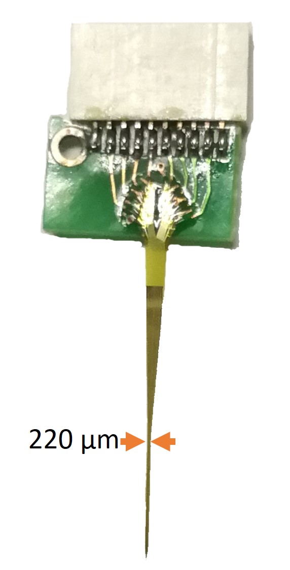
Figure 1. The picture of the MR-compatible microelectrode array
The shaft width of the distal thin part
is 220 µm. (patent
application in progress)
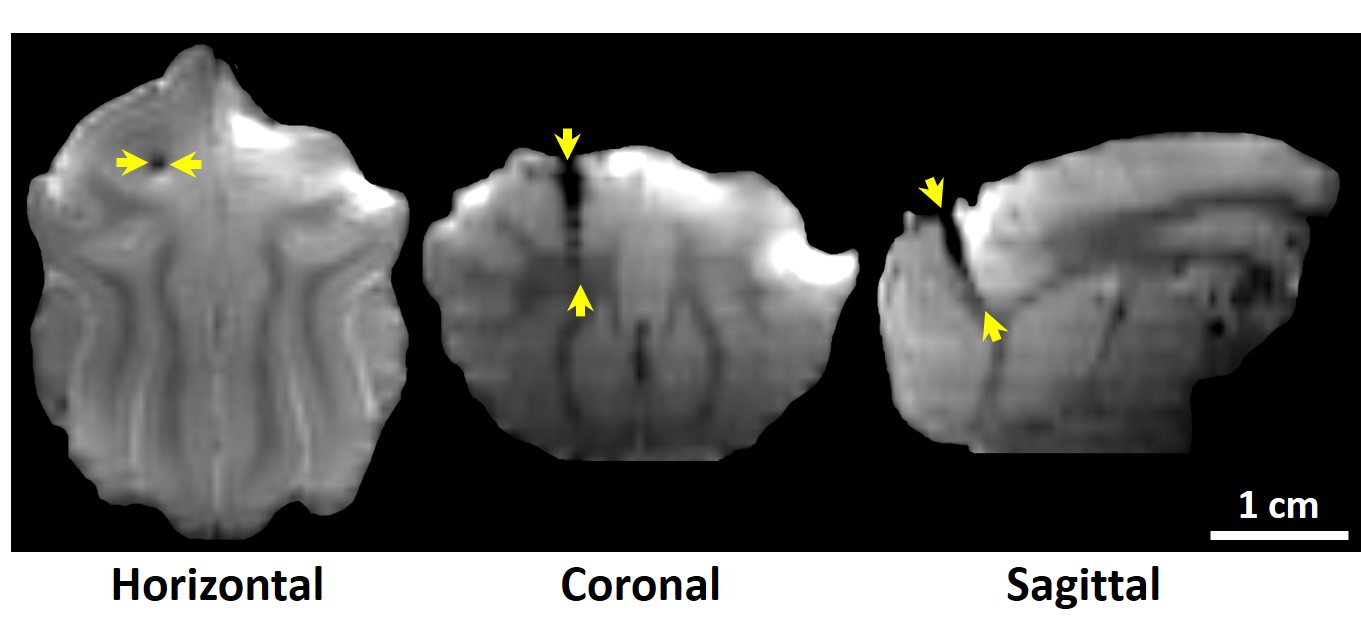
Figure 2. Reconstruction of the T1-weighted
images in
horizontal, coronal and sagittal views.
The MR-compatible
microelectrode array implanted in cat brain showed that in horizontal
view the
distance between the arrows was 1 mm and the distance between the arrows was 7.5
mm in
both coronal and sagittal views.
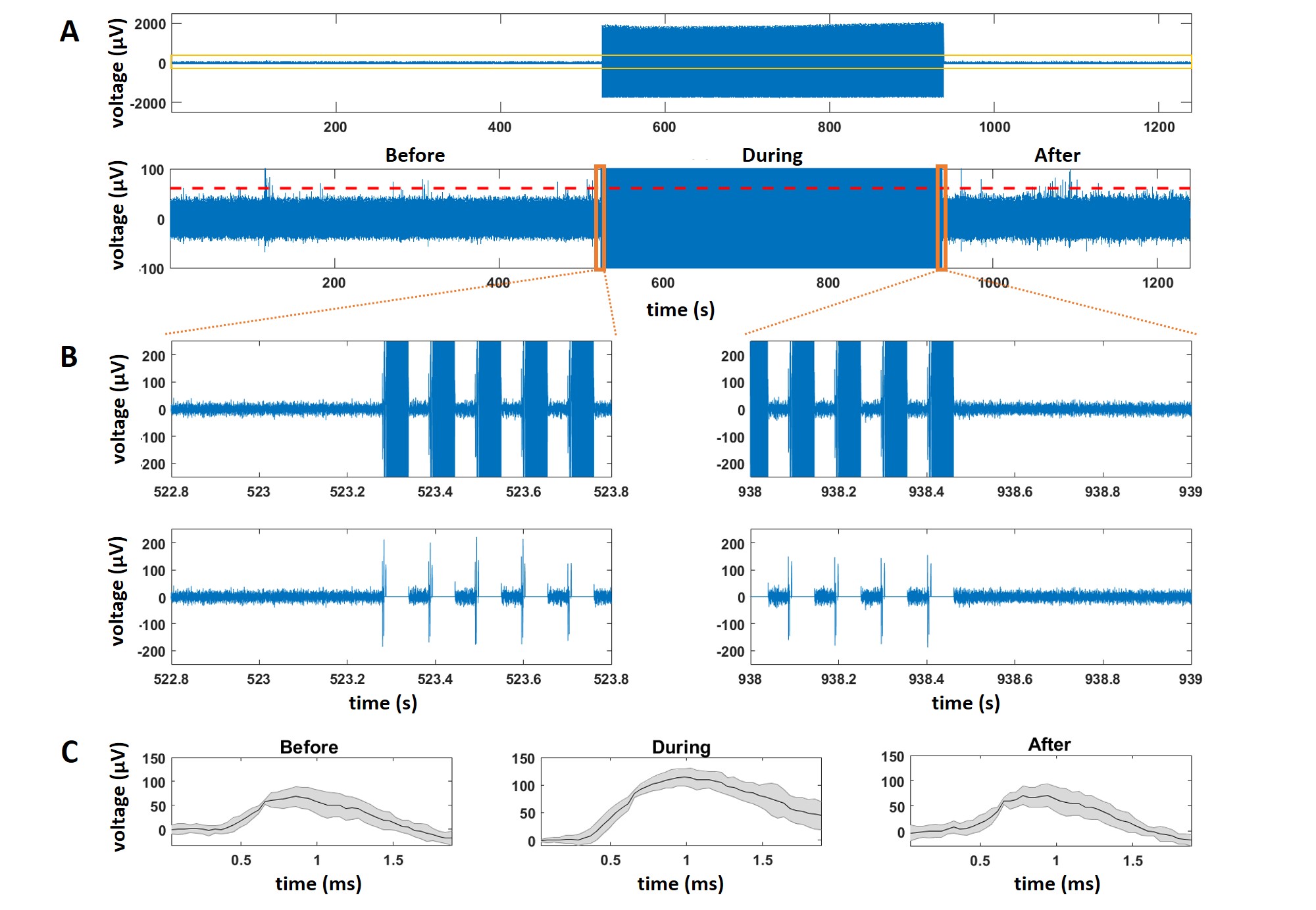
Figure 3. Post-processing results of the continuous
spike signals recorded before, during and after the EPI scanning. (A) the whole
length of the signal in one channel. (B) magnified signal segments in orange
rectangles. (C) spike sorting results of segments before, during and after EPI
scanning.