3550
Comparing Fiber Orientation Estimates from CLARITY and Diffusion MRI in Macaque Visual Cortex1Signal Processing Lab (LTS5), Ecole Polytechnique Fédérale de Lausanne, Lausanne, Switzerland, 2Department of Radiology, Stanford University, Stanford, CA, United States, 3CNC Program, Stanford University, Stanford, CA, United States, 4Department of Electrical Engineering, Stanford University, Stanford, CA, United States, 5Department of Computer Science, University of Verona, Verona, Italy, 6Radiology Department, Centre Hospitalier Universitaire Vaudois and University of Lausanne, Lausanne, Switzerland, 7Department of Bioengineering, Stanford University, Stanford, CA, United States, 8Department of Psychiatry and Behavioral Sciences, Stanford University, Stanford, CA, United States, 9Howard Hughes Medical Institute, Stanford University, Stanford, CA, United States
Synopsis
Tissue clearing techniques offer new possibilities for reconstructing precise 3D axons trajectories. Here, we cleared a 1.5cmx1.3cmx0.3cm cuboid of rhesus macaque visual cortex using CLARITY 3D histology with a neurofilament stain to highlight axonal projections and compared the CLARITY-based fiber orientation estimate to a diffusion tensor MRI atlas. We found better agreement in grey matter than in white matter, potentially reflecting difficulties estimating the structure tensor in highly saturated regions of the CLARITY sample. This work demonstrates one of the largest and highest quality CLARITY cuboids from a macaque brain and explores key steps in the co-registration and analysis required to make a robust comparison against DTI data.
Purpose
To compare fiber orientation estimates derived from CLARITY1 and a DTI atlas in rhesus macaque visual cortex.Methods
MRI AND CLARITY 3D IMAGING ACQUISITION
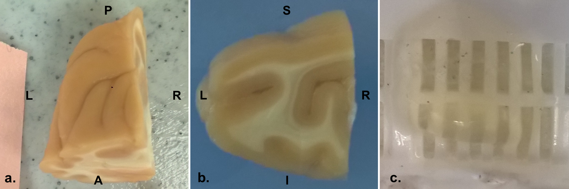
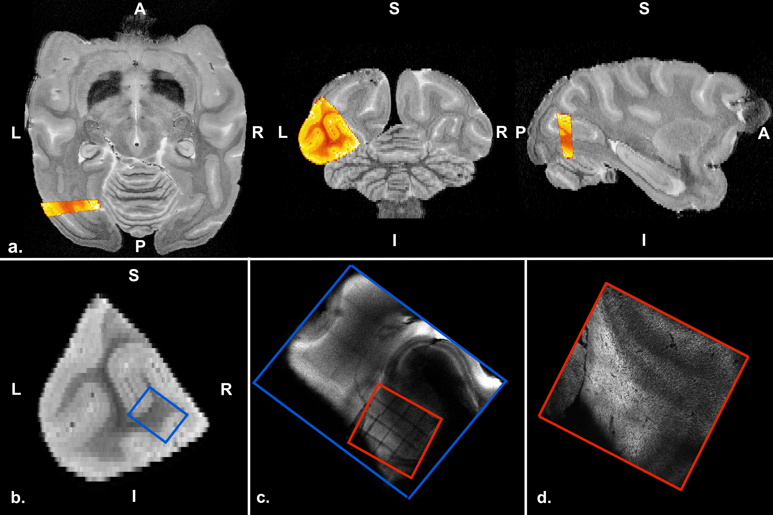
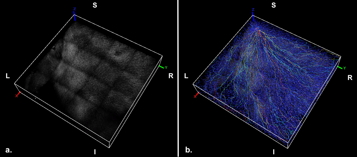
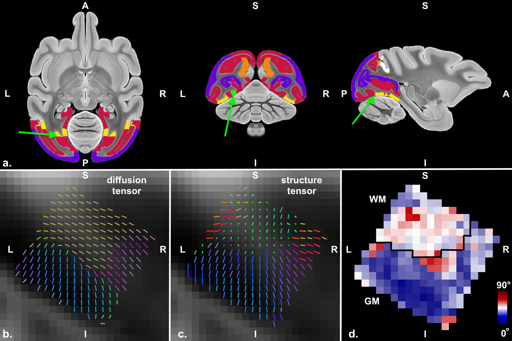
A whole postmortem fixed rhesus macaque brain was scanned on a Bruker BioSpin MRI 7T animal system with a Turbo RARE T2 weighted sequence: resolution 0.15x0.15x0.5mm, TE=53.4ms, TR=25s. The brain was then cut and the lateral posterior part of the left hemisphere (LLP, Figure 1a), was extracted and cleared using the CLARITY protocol2 and stained for neurofilaments (NF) using the SWITCH protocol3. A slab in the middle of the tissue block (LLP4, Figure 1b), was chosen for the analysis. The LLP4 cleared slab (Figure 1c), was imaged with a 2 photon microscopy at 1.5μm isotropic resolution generating a stack of 334 images of pixels size 1769x1859 (Figure 2d). An overview image of the LLP4 was taken with a confocal microscope to localize the 2 photon microscopy images (Figure 2c). The 3D histological images were processed in Fiji4 for bleach correction, blurring reduction using Gaussian filtering with a kernel size 1/10 of the image dimension, median filtering with pixel size 1, and finally contrast and brightness were adjusted. Fiber orientation from the histological 3D CLARITY data were estimated using the structure tensor6, Figure 5b.
The CLARITY results were compared against a high resolution (0.15mm isotropic) macaque DTI brain atlas from the Center for In Vivo Microscopy (CIVM)5, Duke University.
CO-REGISTRATION
Two co-registration pipelines were applied: 1) to localize the CLARITY in the whole brain and have an initial starting point for the registration; 2) vector field rigid registration to refine the co-registration based on the internal tissue structure. The T1 of the LLP4 was co-registered to the T2 structural whole brain data (Figure 2a) with manual initialization + generic elastix registration using 3D Slicer6. The location of 2 photon microscopy images (Figure 2d and 4 in 2D and Figure 3 in 3D) to confocal microscopy images (Figure 2c) was recognized by image contrast created by fluorescent bleaching during the 2p imaging (Figure 2c, red box). Initially, co-registration of the confocal and T1 images was performed manually. All these step were performed to have an initial registration point for the rigid co-registration of the CLARITY images to the atlas. To refine the co-registration between the whole brain diffusion tensor and LLP4 structure tensor a vector field rigid registration algorithm was developed. The optimization algorithm minimized the angular vector distance while allowing rotation and translation.
Results and discussion
Figure 5a shows in green the position of the 2 photon microscopy image after co-registration to the diffusion tensor atlas. The sample is located in visual area 2, close to the dorsal part of visual area 3.
The tissue was manually segmented into white and gray matter for comparison of the different tissue properties. Figure 5d shows the voxel comparison of the main fiber orientation estimation from the diffusion tensor (Figure 5a) and the structure tensor (Figure 5b). It can be seen that the agreement is higher in the GM compared to the WM regions. We find that structure tensor and diffusion tensor are similar in GM but not in WM where we observe multiple orientations in the CLARITY data but only a single main orientation in the diffusion data. The differences in WM can be due to several reasons: 1) the NF stain in the WM regions in the CLARITY images is very dense (Figure 3a, Figure 4) making the estimation of the structure tensor in that region difficult. The structure tensor seems to run along the orientation of vessels and could pick up orientations that are different from the actual fiber structure 2) possible presence of crossing and fanning in the WM regions close to the GM. Because the diffusion data was taken from an atlas, there was no access to test complicated fiber structures in the diffusion data. Comparison to the atlas instead of the same specimen is furthermore a compound, because the fiber orientation can be different for different monkey specimen in the tested region.
Conclusion
This work demonstrates one of the largest and highest quality CLARITY cuboids from a macaque brain and explores key steps in the co-registration and analysis required to make a robust comparison against DTI data. Our data suggests that CLARITY protocols may need to be adapted for staining of areas of different NF protein densities. Ultimately, tissue clearing techniques that offer visualization of 3D axons trajectories represent a new complementary imaging modality that can help validate diffusion MRI and guide further method development.Acknowledgements
This project was funded by the NIH: R01 NS095985, R01 MH111444, R21 MH116484, S10 RR026351, P41 EB015891, GE Healthcare and the Dana Foundation, Swiss National Foundation 205320_175974, Firmenich EPFL-Stanford Exchange Program Fellowship. Diffusion Imaging data provided by the Duke Center for In Vivo Microscopy NIH/NIBIB (P41 EB015897).References
1. Chung, K. et al. Structural and molecular interrogation of intact biological systems. Nature. 497, 332–337
2. Tomer, R. et al. Advanced CLARITY for rapid and high-resolution imaging of intact tissues. Nature Protocols. 2014 9, 1682–1697
3. Murray, E. et al. Simple, Scalable Proteomic Imaging for High DimensionalProfiling of Intact Systems. Cell. 2015 Dec 3;163(6):1500-14
4. Schindelin, J. et al. Fiji: an open-source platform for biological-image analysis. Nature methods. 9(7): 676-682
5. Calabrese, E. et al. A diffusion tensor MRI atlas of the postmortem rhesus macaque brain. Neuroimage. 2015 Aug 15;117:408-16
6. Budde, M. D. et al. Examining brain microstructure using structure tensor analysis of histological sections. Neuroimage 63, 1–10 (2012).
7. Kikinis, R. et al. 3D Slicer: A Platform for Subject-Specific Image Analysis, Visualization, and Clinical Support. Intraoperative Imaging and Image-Guided Therapy, 2014.
8. Peng, H. et al. V3D enables real-time 3D visualization and quantitative analysis of large-scale biological image data sets," Nature Biotechnology 28, 4, 348-353.
Figures