3218
3D printed-phantoms dedicated to pre-clinical imaging systems for quality controlSylvain Miraux1, Aurélien J Trotier1, Colleen Cardiet1, Stéphane Loubrie1, Laurence Dallet1, Thibaut Faller1, William Lefrançois1, and Emeline J Ribot1
1CNRS - Univ. Bordeaux, CRMSB UMR 5536, BORDEAUX Cedex, France
Synopsis
3D printing is a fantastic tool for creating prototypes. In parallel, pre-clinical imaging systems have been democratized for longitudinal studies of small animal models. However, for these systems, standardized phantoms for quality control do not exist yet. The aim of the work presented here is to show that phantoms of different shapes and sizes can be 3D printed to characterize preclinical imaging systems or sequences developed by research groups. As an example, images were acquired with a 70μm in plane resolution to study the influence of Cartesian and Radial encodings on the spatial resolution using a mouse dedicated phased array coil at 7T.
Introduction
3D printing is a fantastic tool for creating single objects or prototypes. With the democratization of these systems, every research laboratory can be equipped with a 3D printer for a reasonable cost. In parallel, pre-clinical imaging systems have also been extended in universities and industries through the creation of imaging facilities. They allow researchers to carry out longitudinal studies on animal models, genetically modified for example. However, compared to the clinical imaging systems that possess a quality control phantom (American College of Radiology Phantom ACR), standardized phantoms do not exist for these preclinical systems. These phantoms are necessary to ensure a quality control of the magnets, to ensure their stability and to compare the efficiency of the multiple sequences that scientific teams develop. Due to the very small size of the animals or objects analyzed at high magnetic field, pre-clinical MRI phantoms are difficult to build. The aim of the work presented here is to show that phantoms of different shapes and sizes can be created using a 3D printer to characterize preclinical imaging systems or sequences developed by research groups.Methods
Different phantoms were created with 3D software like "Cinema 4D (Maxon, DE)" or "Blender (https://www.blender.org, OpenSource Software)". They were then printed using a FormLabs "Form 2" printer (Formlabs, Inc., MA, US). The printer has a spatial resolution of up to 50μm depending on the type of resin used. A classic "Clear" resin was used for the current studies. These phantoms contained a holder for vials (Figure 1a, b) and/or spatial-resolution patterns with specific shapes (round, circle, square, … Figure 1). These phantoms were then incorporated into 50, 15 or 6 mL tubes and filled with different concentrations of Gadolinium or water. The acquisitions were carried out on a 7T Bruker (Germany) Biospec MR system equipped with a Gradient system capable of 670 mT/m. A 72 mm diameter coil was used for transmission and reception. A phased array volumic receive only coil (RapidBiomed, Germany), dedicated to mouse body imaging, was also used (4 channels, 20 mm diameter). Standard spin echo, gradient echo and EPI sequences were tested. 2D and 3D UTE radial sequences were tested with a decreasing number of spokes (Nyquist, Nyquist/2, Nyquist/4 and Nyquist/8).Results
Printed phantoms were imaged using fields of view ranging from 3.5 cm to 1.8 cm and spatial resolutions from 180 μm to 70 μm. The precision of the printing enabled to accurately create any type shape of 200μm spatial resolution. The different concentrations of Gadolinium are visible on the phantoms (Figure 2) whatever the sequences used. The resolution can also be measured on the same phantom on slice 2. Nevertheless, the susceptibility artifacts occurring when using and EPI sequence preventing the detection of the rectangle pattern (arrows). Images acquired with a phased array mouse body dedicated probe were obtained using high spatial resolutions (70μm) (Figure 3). It is therefore possible to study the homogeneity of the probe with this phantom containing different patterns. The spatial resolution and the artefacts inherent to radial sequences can also be evaluated. It enabled to characterize the influence of acceleration on the signal line profiles and the sharpness of the images Figure 4).Discussion
3D printers can create phantoms suitable for the study of contrast, spatial resolution, Point Spread Function (PSF) and can be adapted to the configuration of pre-clinical MRI systems (gradients, probes) or sequences used. Any type of phantoms can be imagined to also measure the precision of the slice thickness, the gradients linearity or the stability of the MRI systems over time. These printed phantoms can be used for many cases: student training, quality control of imaging systems or the development of new MR sequences.Conclusion
Each pre-clinical laboratory or imaging facility can be equipped with 3D printers to better characterize pre-clinical imaging systems. While there are no standard phantom such as for clinical MRI, home-made phantoms appear as an interesting alternative for systems dedicated to small animal imaging. 3D printers can also be used to create compatible MRI systems suitable for the study of small animals (bed, stereotaxic support, support for anesthesia, ...).Acknowledgements
No acknowledgement found.References
No reference found.Figures
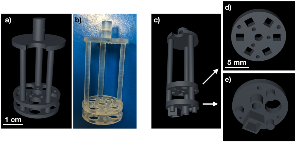
Figure 1: Example of 3D printed prototypes for preclinical MRI. a) 3D view of a vial holder incorporating a resolution pattern and its corresponding picture in b). c) to e) A phantom dedicated to the study of spatial resolution in a mouse dedicated probe.
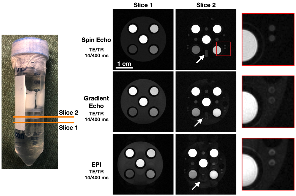
Figure 2: Examples of images obtained with same TE and TR (14/400ms) on the phantoms shown in Fig 1a). Three sequences were used, Spin Echo, Gradient Echo and segmented EPI. The influence of the sequences used to image the phantom on the spatial resolution can be visualized on the last column.
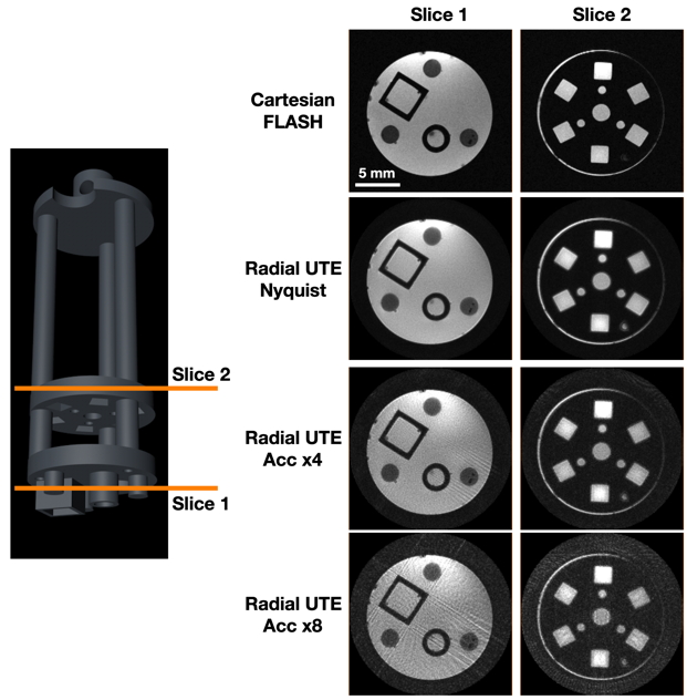
Figure 3: Example of images obtained with the 3D printed prototype of Figure 1 c) to e). Images were acquired with a FLASH sequence with a Cartesian encoding and with an UTE sequence, using a radial encoding and increasing acceleration factors.
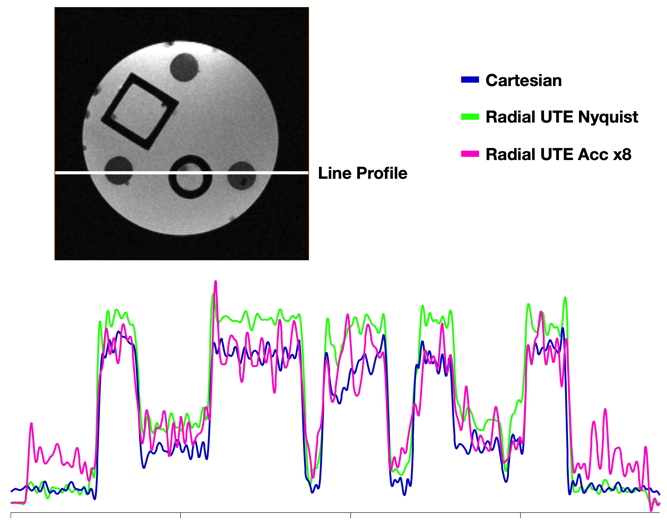
Figure 4: Line profiles obtained on images of Figure 3/slice 1 for cartesian encoding, radial, and accelerated (x8) radial encodings.