2639
Localization of the habenula and stimulating electrodes in pre/post-DBS surgery using MRI1Department of Radiology, Ruijin Hospital, Shanghai Jiaotong University School of Medicine, Shanghai, China, 2Department of Radiology, Wayne State University, Detroit, MI, United States
Synopsis
Deep brain stimulation of the lateral habenula is a common approach to treat refractory depression and other psychiatric diseases. It is very important to know the exact position of the habenula before positioning the electrodes. We conducted phantom experiments using a clinical DBS wire to determine the characteristics of the artifacts stemming from the electrodes and also scanned 6 pre/post-DBS patients on a 1.5T scanner. Both T2W TSE and high resolution GRE imaging clearly visualized the electrodes through the geometric distortion artifacts. 3D T1 MPRAGE, T2W TSE and 3D GRE provided a rapid protocol for scanning patients pre/post-DBS treatment.
INTRODUCTION
Deep
brain stimulation (DBS) is a neurosurgical procedure involving the implantation
of a medical device called a neuro-stimulator, which sends electrical impulses,
through implanted electrodes, to specific targets in the brain (brain nuclei)
for the treatment of movement and neuropsychiatric disorders [1, 2].
The most widely used DBS wire has a linear array of four cylindrical contacts
(electrodes) that can be selectively turned on depending on their placement and
the specific area of the brain to be stimulated. DBS of the lateral habenula is
one current treatment for refractory depression and other psychiatric diseases.
It is very important to know the exact position of the habenula before DBS
operation[3]. The habenulae are a very small pair of nuclei only 3mm
in diameter located in the triangular depression of the third ventricle. They usually
require high resolution T1 weighted (T1W) or T2W imaging to be visualized.
These sequences can be and are used to help guide the placement of the DBS
leads. However, with respect to the anatomical target of interest, the final
position of the DBS electrodes is not fully known until the postoperative
imaging is performed. Placing the leads as close to the target as possible is
critical because the physician must select appropriate stimulus parameters for the
best patient response[4]. Our goal in this study was to set up the
best MRI protocol for preoperative visualization of the habenula and postoperative
visualization of the DBS electrodes. METHODS
Imaging was performed using a
1.5T scanner (Magnetom Aera; Siemens Healthineers, Erlangen, Germany). Phantom experiments were performed using a clinical DBS
wire (L1302, PINS, Beijing, China) to determine the precise characteristics of
the artifact of the electrodes. Six pre- and post- habenula DBS patients (F/M:2/4, age:
31.4±8.7) were also scanned. The imaging parameters were: 1) high resolution T1W
MP-RAGE: TR= 2200 ms TE= 1.94 ms, field of view (FOV) =
240 x 240mm2, matrix size= 320x320, slice thickness =1.5 mm,
acquisition time=6'18''; 2) T2W TSE images: TR= 6590 ms, TE= 95 ms, coronally and transversally scanned, acquisition time=04'19''
and 04'05'', respectively, these were acquired using the same in-plane
resolution as the T1W MP-RAGE images; and 3) Gradient echo(GRE) images: TR=20
ms, TE=5 ms, flip angle=5°, FOV=240 x 240mm2, matrix size= 320x320, slice
thickness =1.5 mm, acquisition time=04'25''.
The phase information from the GRE scan was used to determine the position of
the wire by locating the dipole effect and stepping back one slice to find the
end of the wire. RESULTS
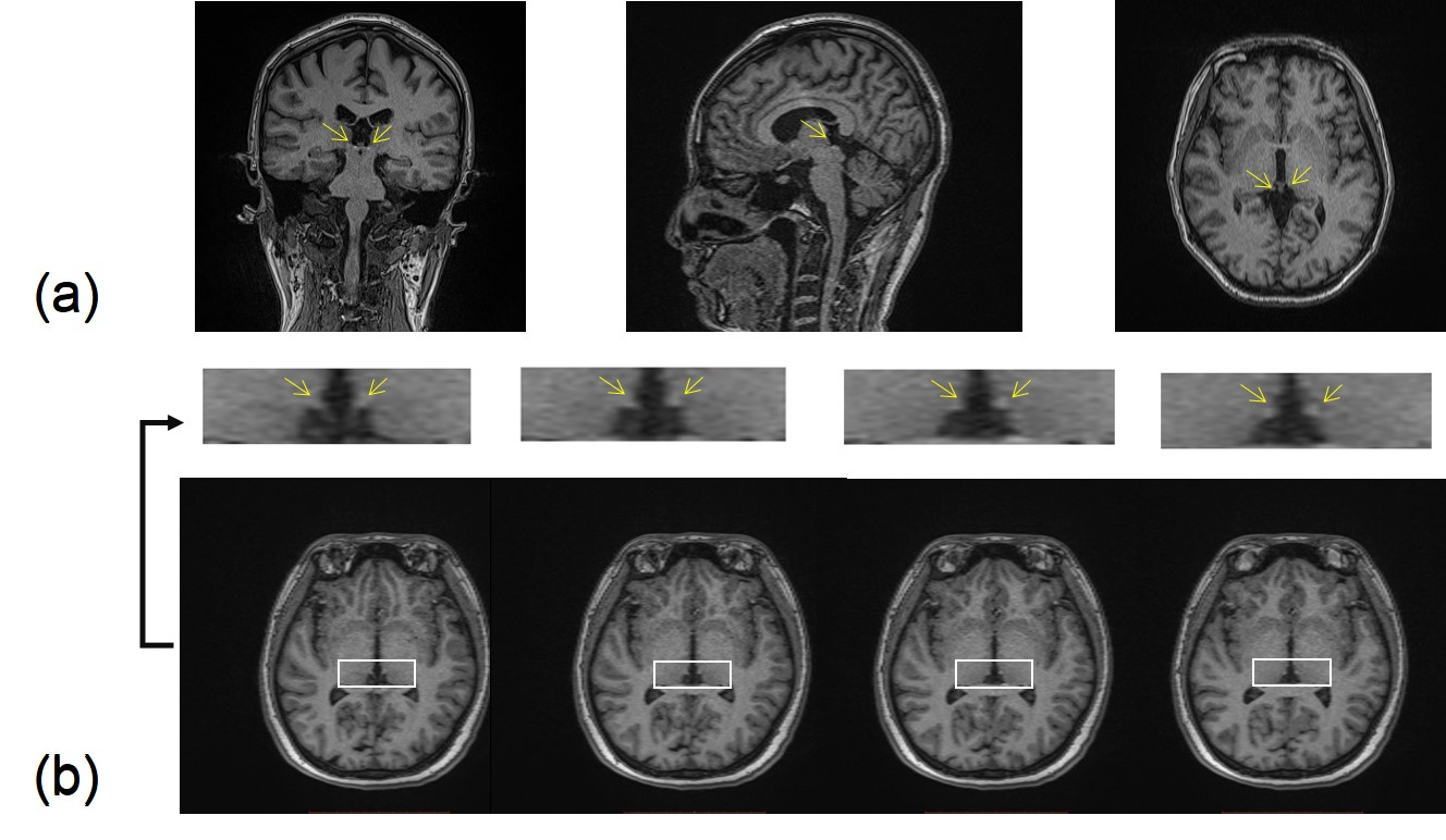
High resolution T1W MP-RAGE provided
detailed images of the whole brain in 3D and were able to clearly show the habenula
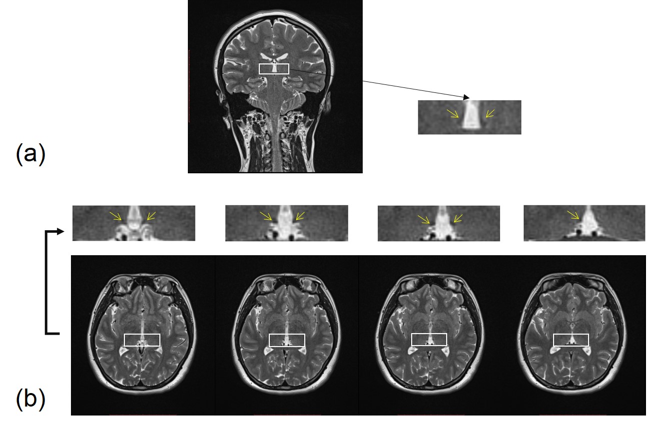
(Figure 1). High resolution coronal T2W TSE images were
able to show both left and right Hb thanks to the contrast with the cerebral
spinal fluid (CSF). The transverse T2W TSE images were also able to show the Hb
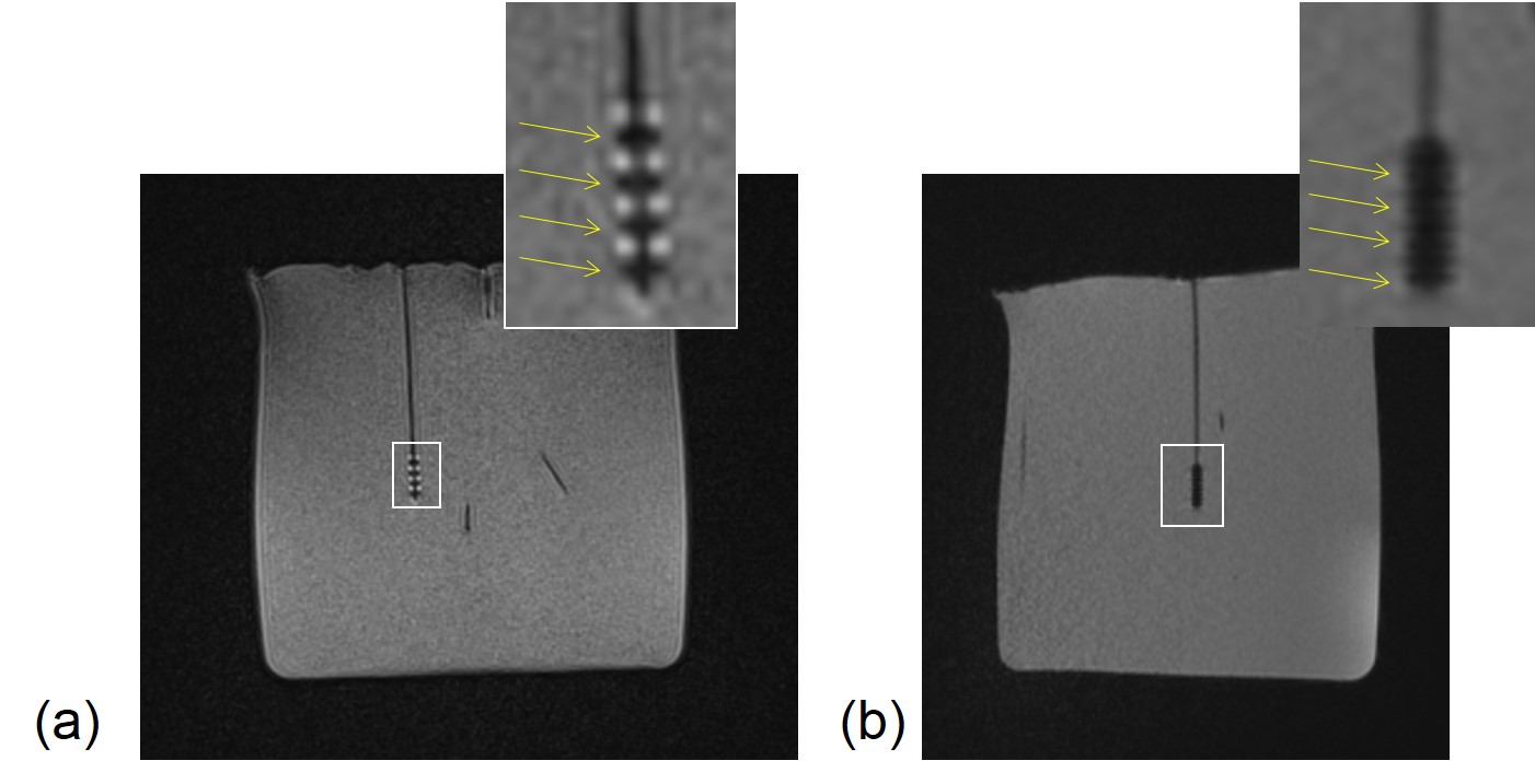
clearly in two or three successive slices (Figure 2). Both
T2W TSE and high resolution GRE imaging were able to visualize the electrodes
through the unique geometric distortion artifacts that highlighted each
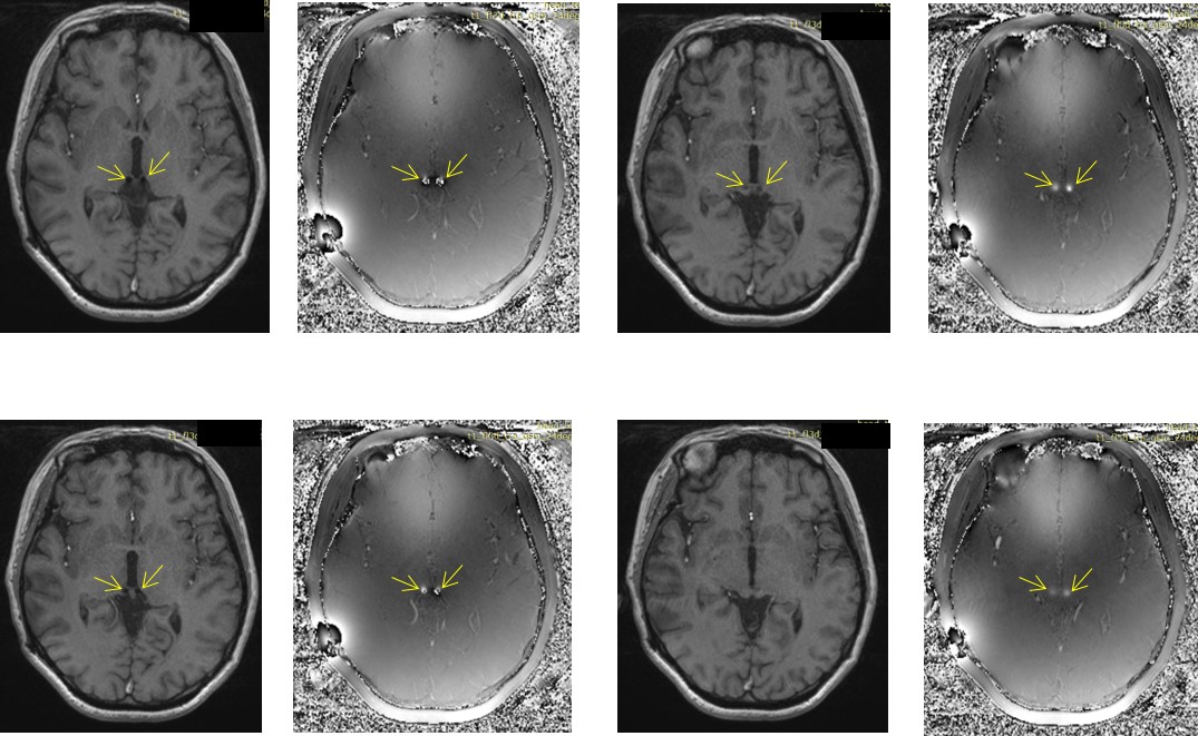
electrode (Figure 3). Further, the end of the wire could be determined
using the phase information highlighting the dipole effect (Figure 4). In all
cases with DBS treatment, the artifacts were consistently seen and both the
location of the electrodes and the end of the wire were clearly identified.
DISCUSSION
Both
high resolution T1W MP-RAGE images and T2W TSE show excellent contrast for the
Hb and are complementary to each other. On the other hand, high resolution GRE
imaging provides excellent post-operative visualization of the electrodes. The
banding artifacts caused by the susceptibility changes in the electrode
material and the abutting material separating the 4 electrodes proved to be a
useful means by which to localize and identify the four electrodes of the DBS
wire. The high resolution and high bandwidth help constrain the artifacts
exactly in the area of the electrodes. The dipole effect see in the phase
images was an effective means to locate the end of the wire. Using
susceptibility mapping may provide an alternative approach for visualizing and
determining the end of the wire. Finding the electrodes is important because it
helps to ascertain which ones should be used to treat the patient.CONCLUSION
In conclusion, 3D T1 MPRAGE, T2W TSE and 3D
GRE provided a rapid protocol for imaging the brain for the patient pre/post-DBS
treatment.Acknowledgements
The authors thank Chencheng Zhang and Yingying Zhang (Department of Functional Neurosurgery, Ruijin Hospital Shanghai Jiaotong University School of Medicine, Shanghai, China) for participating in data collection.References
[1] Simon L, Martijn B, Ludvic Z, et al. Bilateral adaptive deep brain stimulation is effective in Parkinson's disease. J Neurol Neurosurg Psychiatry, 2016, 87(7):717-721.
[2] Dandekar M P, Fenoy A J, Carvalho A F, et al. Deep brain stimulation for treatment-resistant depression: an integrative review of preclinical and clinical findings and translational implications. Mol Psychiatry, 2018.
[3] Lahue S C, Ostrem J L, Galifianakis N B, et al. Parkinson's disease patient preference and experience with various methods of DBS lead placement. Parkinsonism & Related Disorders, 2017, 41.
[4] Lee M W, De Salles A A, Frighetto L, et al. Deep brain stimulation in intraoperative MRI environment - comparison of imaging techniques and electrode fixation methods. Minim Invasive Neurosurg, 2005, 48(01):1-6.
Figures