2202
Correction of B0 Field Distortion Induced by Stainless Steel Nuss Bar in Cardiac MRI Using Permanent Magnets1University of Texas Southwestern Medical Center, Dallas, TX, United States, 2Children's Health, Dallas, TX, United States
Synopsis
Pectus excavatum is often corrected by the Nuss procedure, in which a metal bar (usually made of stainless steel) is inserted horizontally into the chest cavity. MRI examination is important to assess the cardiac function with a focus on the right heart. The metal bar causes susceptibility artifacts in cine MRI. We explore the feasibility to improve the B0 field homogeneity using a field correction device to be placed on the surface of the chest utilizing permanent magnets. A device was constructed based on computer simulations. The device generates magnetic multipole fields and effectively improved B0 homogeneity in a phantom.
Introduction
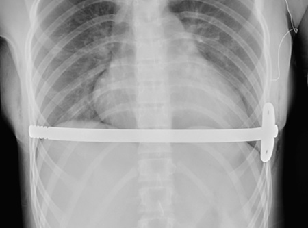
Pectus excavatum 1 is the leading congenital chest wall deformity in children, which produces a concave appearance at the sternum. The deformed chest wall compresses the heart and decreases the cardiac function 2. The condition is often corrected by the Nuss procedure 3, in which a metal bar is inserted horizontally into the chest cavity (Figure 1). In patients with pectus excavatum, MRI examination is becoming important to assess the cardiac function with a focus on the right heart. The metal bar in most cases is stainless steel, and there is an obliteration of signal intensity in cine MRI of the heart due to the close proximity of the metal bar. Although techniques such as O-MAR and SEMIC have been available for imaging near metal implants, they are presently unable to perform cardiac function measurements. Nuss bars made of titanium are commercially available with less MRI artifact 4, but they are less practical in clinical practice due to much higher prices. Here, we explore the feasibility of improving the B0 field homogeneity using a field correction device utilizing permanent magnets.Materials and Methods
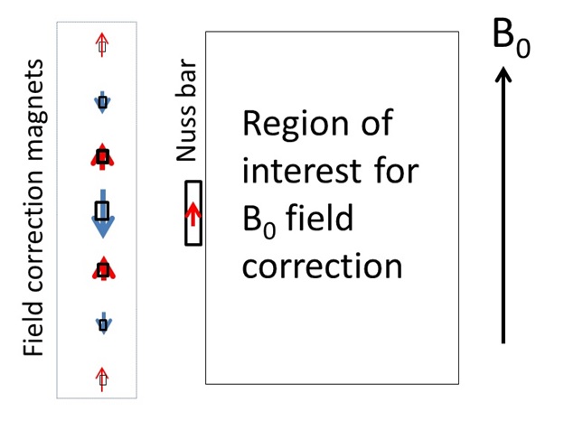
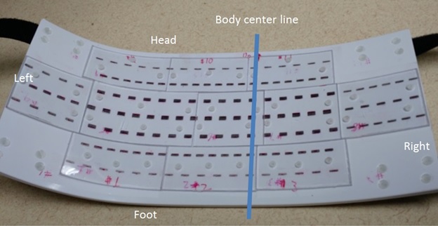
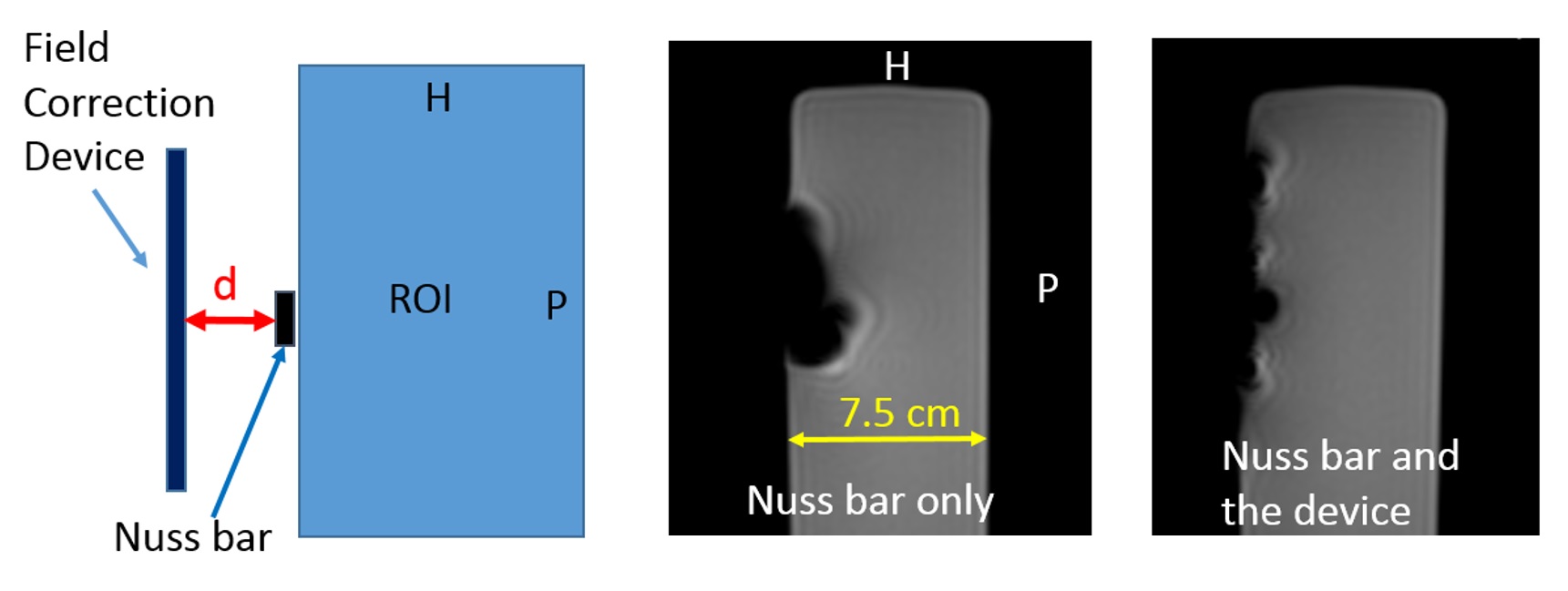
Typically, a Nuss bars is 300 mm long, 12.5 mm wide, 2.5 mm thick, bent to conform to the shape of the ribcage, and 20 mm beneath the chest surface. The total induced magnetic moment of the horizontal bar at 1.5T is 0.03 A∙m2, and is uniformly distributed along its length. The field correction device would be placed on the chest surface and provide multipole magnetic field 5 to mitigate the B0 inhomogeneity. In the area near the heart, permanent magnets are arranged in 7 parallel lines with magnetic moments alternately opposed to or aligned with the B0 field (see Figure 2). The spacing between the lines was 15 mm and the length was 180 mm. Further away from the heart, 3 lines (50 mm and 40 mm long, respectively) were used on right and left sides. Permanent magnets (NdFeB magnets, grade N30AH, Pacific PAC Technologies, Inc.) were custom made with different sizes and the magnetic moment was measured at 1.5T with the magnetization parallel and anti-parallel to the B0 field 6. Permanent magnets were mounted on a piece of rigid PVC plate which was bent to conform to the contour of the chest of a typical patient (Figure 3). Although the magnets were discrete entities on the device, they approximated lines of magnetic dipoles. Computer simulations were performed to determine the magnetic dipole moment line density mi of the correction magnets:
$$ min. \int_{ROI}^{ }(B_{0,NussBar}(x,y,z)-B_{0, Device}(x,y,z))^2dV-\lambda\cdot\sum_{z\geq0} m_i^2 $$
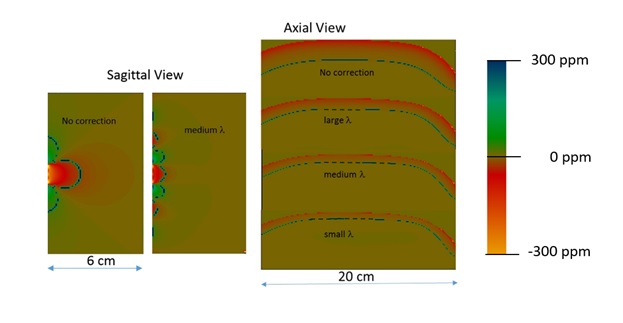
The first term minimized the field inhomogeneity over an ROI where uniform B0 is desired, and the second term is for regularization which required the total absolute value of magnetic moment of correction magnets to be small. Magnets below the center line (z<0) were excluded from the sum because they are not independent. The parameter λ balanced the two terms. The equation was readily solved by a least squares routine using IDL. The device was constructed assuming λ=7x10-15 T2mA-2 (medium λ in Figure 4), and was tested on a rectangular phantom using an FFE pulse sequence used for cine cardiac MRI on an Ingenia 1.5T scanner.
Results
Computer simulation showed improvement of B0 homogeneity (Figure 4). Inside a 1.5T MRI scanner, the total magnetic moment of the central horizontal diploe line of the device is -0.73 A·m2, and the net magnetic moment of the entire device is 0.02 A·m2. The optimal distance between the device and the Nuss bar was found to be 20 mm. MRI measurements at 1.5T are shown in Figure 5 for a sagittal plane. The area with obliterated signal shrank in the AP direction and expanded in the HF direction and decreased 41% from 926 mm2 to 546 mm2.Discussion
Previously, field correction device for MRI utilizing permanent magnets has been described for stainless steel orthodontic appliances 7, where correction magnets are placed very closely to the induced magnetic dipole moment in orthodontic appliances to match their amplitude and distribution, and the region of interest for field correction is relatively far away. In the current situation, the ROI for field correction is close to the Nuss bar and correction magnet is not close to the source of inhomogeneity. In this case we rely on multipole magnetic fields from the device to improve B0 homogeneity. Patient studies will be conducted next to see if meaningful measurement of cardiac function is feasible.Conclusion
A field correction device can improve B0 homogeneity in the presence of a stainless steel Nuss bar.Acknowledgements
The study received support from the UTSW Department of Surgery Discovery Grant.References
1. Oezcan S, Attenhofer Jost CH, Pfyffer M, et al. Pectus excavatum: echocardiography and cardiac MRI reveal frequent pericardial effusion and right-sided heart anomalies. Eur Heart J Cardiovasc Imaging. 2012;13(8):673-679.
2. Saleh RS, Finn JP, Fenchel M, et al. Cardiovascular magnetic resonance in patients with pectus excavatum compared with normal controls. J Cardiovasc Magn Reson. 2010;12:73.
3. Nuss D. Recent experiences with minimally invasive pectus excavatum repair "Nuss procedure". Jpn J Thorac Cardiovasc Surg. 2005;53(7):338-344.
4. Topper A, Polleichtner S, Zagrosek A, et al. Impact of surgical correction of pectus excavatum on cardiac function: insights on the right ventricle. A cardiovascular magnetic resonance studydagger. Interact Cardiovasc Thorac Surg. 2016;22(1):38-46.
5. Jackson JD. Classical Electrodynamics. 3rd ed: John Wiley & Sons, Inc.; 1999.
6. Li S, Wang ZJ, Leigh JS. Magnetic susceptibility measurement by MRI - a dipole field method. Paper presented at: ISMRM 1998; Sydney, Australia.
7. Wang ZJ, Park YJ, Seo Y, Morriss MC, Rollins NK. Reducing brain MRI artifacts caused by ferromagnetic orthodontic appliances using permanent magnets. Paper presented at: ISMRM 2016; Singapore.
Figures