2119
Optimization of cardiac functional magnetic resonance imaging at 7T1Medical College of Wisconsin, Milwaukee, WI, United States
Synopsis
In this study, we provide preliminary data from phantom and in vivo scans for optimizing 7T cardiac functional imaging. The results show that high-quality cardiac functional imaging can be achieved at 7T by optimizing the scan settings and imaging parameters, especially to mitigate B1 inhomogeneity effects. Adjusting the imaging flip angle and adding dielectric pads to the imaged region-of-interest could help improve B1 homogeneity and reduce signal nulling effects. High spatial and temporal resolutions and improved tagging persistence achieved at 7T allows for accurate global and regional cardiac function measurements and access to information not available at lower field strengths.
INTRODUCTION
With 7T MRI scanners from different vendors being clinically approved, it is expected that 7T imaging will be soon adopted in clinical practice [1,2]. Enhanced signal-to-noise ratio (SNR) at 7T can be traded for improved image quality, higher temporal or spatial resolution, or shorter scan time. In this study, we provide preliminary data from phantom and in vivo scans for optimizing 7T MRI cardiac functional imaging towards improving image quality and alleviating artifacts associated with high-field MRI.METHODS
A static phantom and four healthy subjects were scanned on a 7T GE MRI scanner using 32-channel transceiver coil. The modular coil array consists of 8 independent blocks, each containing 4 transceiver elements, whose phase settings were optimized based on simulations for a multi-oblique plane mimicking a standard cardiac view [3].
The effect of the imaging flip angle on image quality was assessed in a phantom scan. A liquid-filled bottle was imaged using a gradient-echo cine sequence. The scan was repeated with flip angles ranging from 1⁰ to 120⁰. Forward simulation was conducted on the resulting images to generate an estimate of the B1 transmission frequency field in the imaged slice, as previously described [4]. The advantage of this actual imaging flip-angle (AIF) B1 mapping technique is that it uses pulsed steady-state signal acquisitions, which alleviates the need for long relaxation delays between sequence repetitions and is not sensitive to T1 variation.
Both short-axis and long-axis cardiac cine and tagging images were acquired in the scanned volunteers. The coil placement and imaging parameters were optimized to improve image quality. The effect of the imaging flip on myocardium SNR and myocardium-to-blood contrast-to-noise ratio (CNR) was studied. The effects of using dielectric pads to improve B1 homogeneity were investigated. Finally, the imaging parameters were optimized to improve cine spatial and temporal resolutions and tagging persistence.
RESULTS
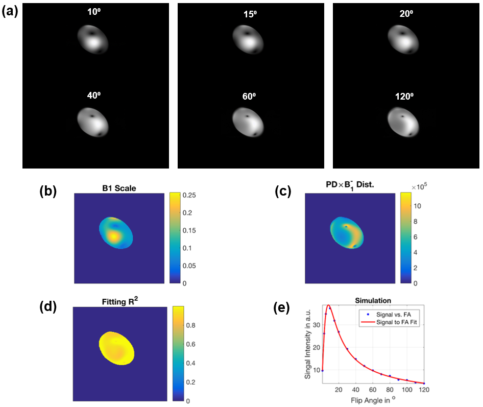
Figure-1 shows results from the phantom experiment. The figure shows variable signal intensity and regions of signal loss across the phantom, where signal intensity profile changes with the imaging flip angle. The estimated B1 map and proton density distribution reflect the observed signal intensity inhomogeneity in the imaged phantom. The resulting R2 map shows excellent data fitting, as shown for a certain pixel location in the imaged phantom.
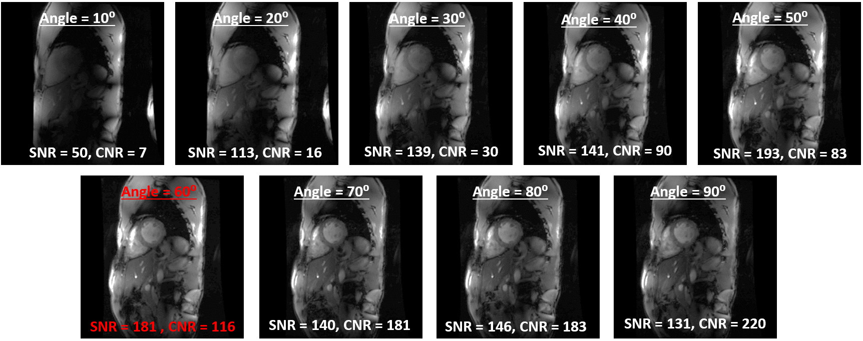
For in vivo scans, we found that moving the coil up towards the chin resulted in improved signal intensity at the basal and lateral heart regions, compared to when the coil was centered on the heart. The imaging flip angle plays a key factor for determining CNR (Figure-2). In contrast to low flip angles (~10-20⁰) that are typically used at 1.5T and 3T fields, much higher flip angle is needed at 7T. Based on the results from this study, a 50-60⁰ flip angle resulted in optimal image quality. In the example shown in Figure-2, a 60⁰ flip angle resulted in optimal SNR/CNR of 181/116, where average SNR/CNR (based on results from our previous studies) is ~30/100 and 40/150 at 1.5T and 3T, respectively.
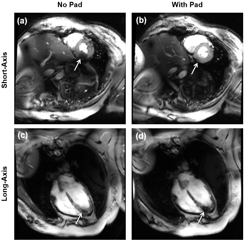
Adding dielectric pads next to the imaged region-of-interest could help improve B1 homogeneity. As shown in Figure-3, adding a dielectric pad underneath the volunteer’s back resulted in minimizing signal nulling at the mid-basal regions of the heart, although it slightly increased the artifact at the apex. Moving the pad anteriorly towards the chest did not help improve image quality compared to when the pad was not used.
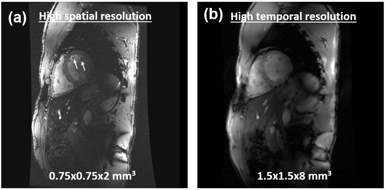
Figure-4 shows high spatial-resolution cine image, which allows for assessing detailed anatomical features compared to low-field MRI. Alternatively, temporal resolution of ~20ms could be achieved. Scan time can be maintained by using parallel imaging, while still maintain adequate SNR.
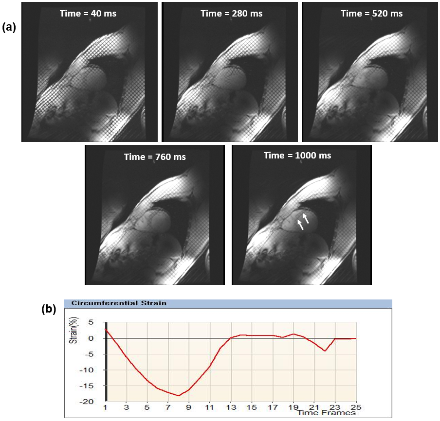
As myocardial T1 is inherently increased at 7T, tagging persistence is significantly increased throughout the whole cardiac cycle (Figure-5), which allows for assessment of heart mechanics till end-diastole, an advantage that is not available at low-field MRI. Optimal flip angle for tagging MRI is 10-15⁰, as larger flip angles lead to rapid taglines fading.
DISCUSSION and CONCLUSION
High-quality cardiac functional imaging at 7T can be achieved by optimizing the scan settings and imaging parameters, especially to mitigate B1 inhomogeneity effects. Adjusting the imaging flip angle and adding dielectric pads to the imaged region-of-interest could help improve B1 homogeneity and reduce signal nulling resulting from standing-wave effects. However, it should be noted that the optimal imaging flip angle and dielectric pad positioning could change from patient to another.
In conclusion, high-field cardiac MRI would allow for accurate global and regional cardiac function measurements and access to information not available at lower field strengths.
Acknowledgements
No acknowledgement found.References
1. Niendorf et al, NMR Biomed, 29:1173-1197
2. Snyder et al, Magn Reson Med, 61:517-524
3. Graessl et al, Magn Reson Med, 72:276-290
4. Yarnyth, Magn Reson Med, 57:192-200
Figures