2038
Towards higher spatial resolution late gadolinium enhancement using 3D Turbo Spin Echo (3D TSE LGE)1Yale University, New London, CT, United States
Synopsis
3D inversion recovery (IR) turbo spin echo (TSE) was investigated for its value in higher spatial resolution 3D late gadolinium enhancement (LGE). Studies in simulations, phantoms and patients found that the SNR is higher with 3D IR TSE, potentially permiting increased spatial resolution, and LGE is feasible.
Purpose
High resolution 3D late gadolinium enhancement (3D LGE) (1) is the only non-invasive imaging method for evaluation of atrial fibrosis and scar, and also improves visualization of complex ventricular infarcts and papillary muscle scar. Particularly, for atrial fibrosis, spatial resolution is the primary limitation for 3D LGE and has led to skepticism about the accuracy of atrial LGE(2). The current spatial resolution for 3D LGE (using a 5 minute scan) hovers around 1.3 x 1.3 x 3 - 4 mm, before zero-filling. This provides an image for which the SNR of blood is about 9 (3). This spatial resolution is not sufficient to separate blood from atrial wall, a 2 mm thick structure. Because SNR is critically low, it is not possible to use standard MRI acceleration methods to accelerate imaging and increase resolution. As determined in a recent study, increasing spatial resolution of LGE paradoxically reduces detection of post-ablation scar (4). This implicates SNR as the critical roadblock to any increase in spatial resolution. We hypothesize that 3D IR TSE (aka variable flip angle TSE, SPACE, CUBE, VISTA)(5,6) will provide greater SNR and therefore permit increased spatial resolution, compared with 3D LGE. Since the development of first LGE methods (7), there have been many innovations in 3D TSE which potentiate its utility in 3D LGE: e.g. shorter echo-spacings with non-selective RF excitations, variable flip angle schemes to achieve specific effective echo times with less SAR, and efficient k-space trajectories that make use of extended acquisition time.Methods
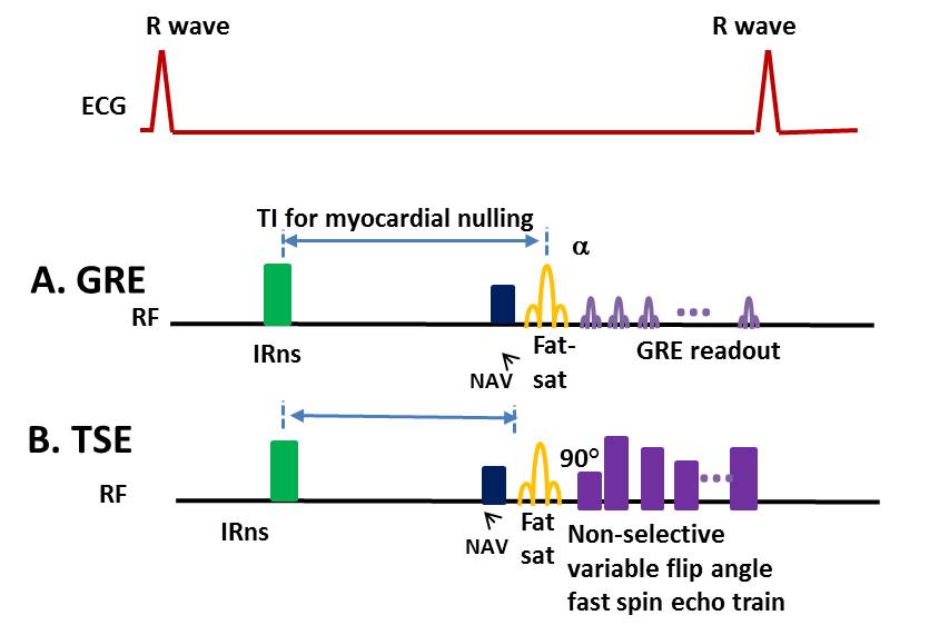
Figure 1 illustrates
the IR GRE and IR TSE sequences. A simulation was performed to estimate SNR for
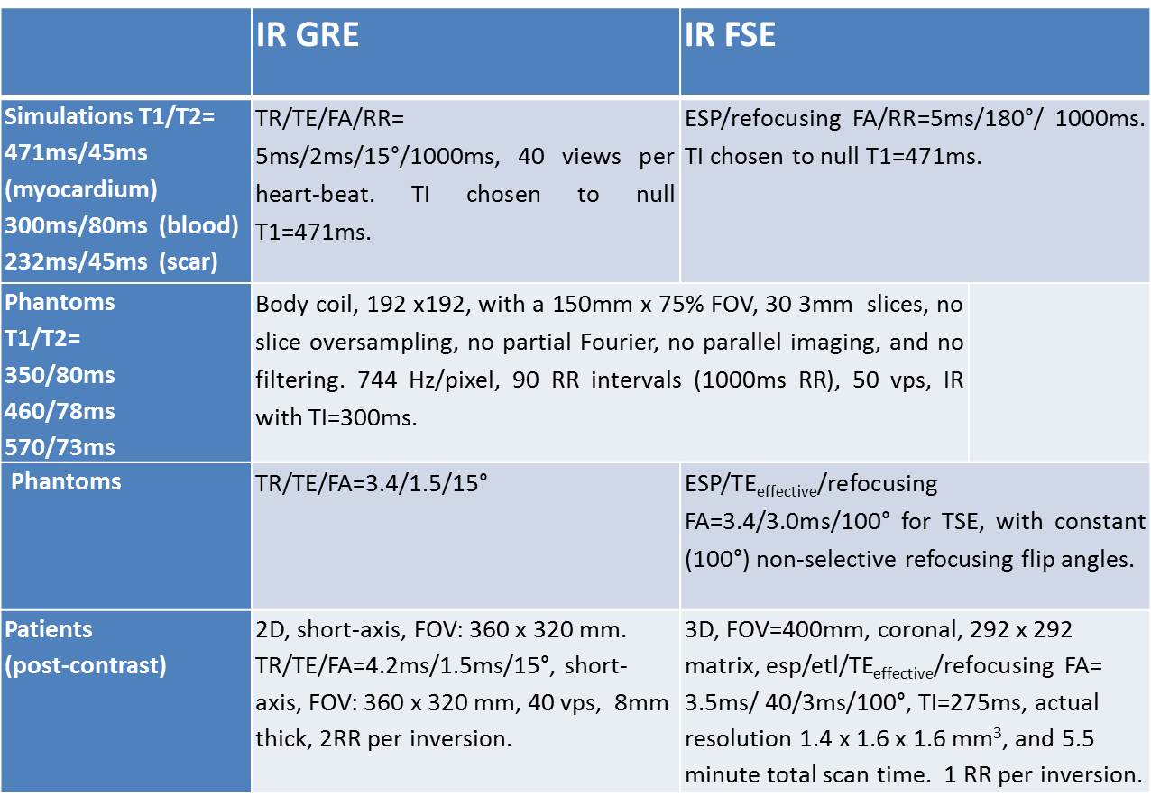
IR GRE and IR TSE. Basic parameters for
the simulation are given in Table 1, and were chosen to be
similar to actual LGE protocol. The inversion time (TI)
was chosen to null myocardial T1.
NiCl Agar phantoms were constructed with realistic
T1 and T2 values, similar to those in post-contrast myocardium. SNR was compared between 3D IR GRE and 3D IR TSE sequences with closely matched scan parameters. Scan parameters are
given in Table 1, and were chosen to reflect the clinical LGE protocol.
The 3D IR TSE protocol was applied in a patient, using inversion recovery, fat-saturation,
navigator-gating, non-selective RFs to keep echo-spacings short, with a coronal slab. Imaging was
performed about 15-20 minutes after injection of 0.2mmol/kg gadobutrol contrast
agent, and immediately following a conventional 2D LGE. Scan parameters are given in Table 1. For IR TSE, the spatial resolution was 1.4 x
1.6 x 1.6 mm3, with 5.5 minute total scan time. This represents a 2-fold increase in spatial
resolution for TSE vs. conventional 3D LGE. Results
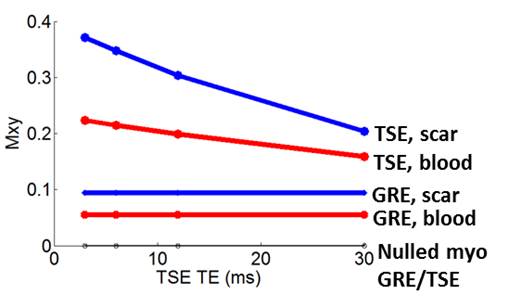
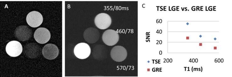
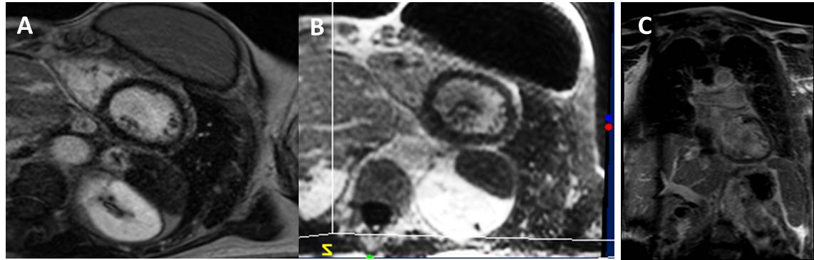
Simulation results are shown in Figure 2. IR TSE provided a 3-fold increase in SNR vs. IR GRE, for enhanced signals at the shortest TEs. Figure 3A-B compares the results of IR GRE and IR TSE in realistic phantoms. Figure 3C shows that SNR for TSE was higher for all bottles, approximately 2-fold. Figure 4 compares LGE with 3D IR TSE, in a patient after contrast-injection. The 2D LGE was acquired in a short-axis plane, while the TSE was acquired in a coronal plane with non-selective RF and reformatted to the short-axis view. The TSE LGE volume has 2-fold increased spatial resolution, compared to that of conventional 3D LGE, and is comparable to the 2D LGE even in this reformatted plane, in which the spatial resolution is lowest.Discussion and Conclusions
TSE introduces several
challenges including T2-decay, which affects SNR and sharpness. Furthermore,
flow and motion in TSE result in artifacts and lost signal. However, there are several advantages to TSE.
The TR is lower at identical bandwidth; 3D IR TSE is less affected by
regrowth of fat, blood and myocardium, throughout the echo train than GRE.
TSE’s major advantage is SNR, as shown here, which can be traded-off for resolution.
In conclusion, TSE LGE
provides increased SNR vs. conventional LGE, theoretically and experimentally,
for protocols with matched parameters.
Furthermore, TSE LGE is feasible in patients, and permits acquisition of
more than 2-fold increased spatial resolution with acceptable SNR. TSE LGE has potential value in visualization
of atrial (8) and ventricular fibrosis.Acknowledgements
This work was partially supported by a grant from the NIH R01HL122560. The authors thank Dr. Daniel Herzka for his ideas concerning TSE.References
1. Peters DC, Wylie JV, Hauser TH, et al. Detection of pulmonary vein and left atrial scar after catheter ablation with three-dimensional navigator-gated delayed enhancement MR imaging: initial experience. Radiology Jun 2007;243:690-695.
2. Appelbaum E, Manning WJ. Left atrial fibrosis by late gadolinium enhancement cardiovascular magnetic resonance predicts recurrence of atrial fibrillation after pulmonary vein isolation: do you see what I see? Circulation Arrhythmia and electrophysiology Feb 2014;7:2-4.
3. Hu C, Huber S, Latif SR, Santacana-Laffitte G, Mojibian HR, Baldassarre LA, Peters DC: REPAIRit: Improving Myocardial Nulling and Ghosting Artifacts of 3D Navigator-Gated Late Gadolinium Enhancement Imaging During Arrhythmia. J Magn Reson Imaging 2018.
4. Chubb H, Karim R, Roujol S, et al. The reproducibility of late gadolinium enhancement cardiovascular magnetic resonance imaging of post-ablation atrial scar: a cross-over study. J Cardiovasc Magn R Mar 19 2018;20.
5. Busse RF, Hariharan H, Vu A, Brittain JH. Fast spin echo sequences with very long echo trains: design of variable refocusing flip angle schedules and generation of clinical T2 contrast. Magnetic resonance in medicine May 2006;55:1030-1037.
6. Mugler JP, 3rd, Kiefer B, Brookeman J. Three-dimensional T2-weighted Imaging of the Brain Using Very Long Spin-Echo Trains. ISMRM 2000, 687.
7. Simonetti OP, Kim RJ, Fieno DS, et al. An improved MR imaging technique for the visualization of myocardial infarction. Radiology Jan 2001;218:215-223.
8. McGann CJ, Kholmovski EG, Oakes RS, Blauer JJ, Daccarett M, Segerson N, Airey KJ, Akoum N, Fish E, Badger TJ, et al: New magnetic resonance imaging-based method for defining the extent of left atrial wall injury after the ablation of atrial fibrillation. J Am Coll Cardiol 2008, 52:1263-1271.
Figures