1607
A “Less-for-More” Concept in Array Coil DesignTsinghua Zheng1, Xiaoyu Yang1, Haoqing Zhu1, and Yong Wu1
1Quality Electrodynamics, LLC, Mayfield Village, OH, United States
Synopsis
We present a novel “Less-for-More” concept for array coil by joining different coils as one RF channel with transmission lines. This concept not only simplifies the coil design but also achieves optimum isolation among all channels by overlapping. A 4-ch 8-loop knee coil at 1.5T was constructed to demonstrate this concept. The test result shows similar signal-to-noise ratio (SNR) at the center to a commercial 1.5T 15-channel Tx/Rx knee coil’s. Furthermore, additional acceleration at g factor 2 in SI direction is also achieved with a 4-ch only coil besides axial accelerations.
Introduction
Since the introduction of the phased array (1) the total number of RF coil channels has been increased steadily. The increased channel number achieves not only better image quality but also improved performance in parallel imaging techniques, such as SENSE, SMASH and GRAPPA(2)(3)(4). However, the increased channel number also brings additional cost and one technical difficulty besides other challenges. The difficulty is to achieve good isolations among all channels for a >16-ch coil. Furthermore, value MR system only has limited number of receiver channels, such as 8-16 channels. This limited number prevents value MR system from being used in very highly parallel imaging applications. The proposed “Less-for-More” concept provides a novel approach to isolate all RF channels, have comparable SNR and still keep high acceleration with significantly reduced number of channels.Theory
If two coils are connected by a lossless transmission line as shown in Fig. 1, then we may derive I2/I1 = (Z0/Z2)/ ((Z0/Z2)cos(α)+j sin(α)) using ABCD matrix, where I1 is the current through the coil 1 , I2 is for the coil 2, Z0 is the intrinsic impedance of the transmission line, α is the phase delay of the transmission line and Z2 is the coil 2 impedance seen by the transmission line. If I1=I2 is intended, then Z2 can be adjusted to satisfy equation mentioned previously for phase delay α. What I1=I2 means is that two coils work as one channel. The final coil frequency adjustment can be done at the coil 1 side. We can use one matching circuit and one LNA to receive both coils as one channel. This approach can be extended to more than two coils. Using this method the coils of the same channel can be put at strategical locations to achieve two goals. The first goal is that each coil can be adjacent to at least one of coils of other channels. This achieves all channels isolation for improved SNR just using overlaps. The second goal is to ensure phase encoding in all x, y, and z directions “seeing” different channels for optimum acceleration because each coil still maintains its unique signal profile. For example, Fig. 2 shows an example of a 4x8 array coil using only 8 channels. The coils with same color are joined together to create 8 RF channels. Each color is adjacent to all other colors so that the isolation can be optimized by the overlaps. This “Less-for-More” concept can also be applied to transmit coil array for pTx application.Method
A 4-channel 8-loop knee coil at 1.5T was constructed to prove this “Less-for-More” concept. Fig. 3 shows the loops layout and how the loops are connected by the transmission lines. Both loops of each channel were carefully tuned so that they act like one channel. Both loops of each channel can observe the double-peak S21 sensitivity profile due to the low input impedance preamplifier. The coil was built on an identical mechanical housing as a commercially available 1.5T 15-ch Tx/Rx Knee coil (5). Both the proposed coil and the commercial 15-ch coil were evaluated using a Siemens 1.5T AERA MRI system and Spin Echo sequence. The phantom used for evaluation is a two-liter cylindrical bottle with the solution of 5gNaCl+3.25g CuSO4 ∙5H2O/liter H2O.Results
Fig. 4 shows the phantom SNR of axial plane for both coils. The “Less-for-More’ coil has 3.3% more SNR than the comparison coil at the center and 25% less SNR at the surface of the phantom. The SNR difference at the center and the surface is because each loop of the same channel needs to carry the whole channel’s noise. The center signals are contributed by most channels while the surface signals are primarily contributed by nearby coils of certain channels. Fig. 5 shows the g-factor maps of both coils in both axial and sagittal planes with acceleration factor 2. As expected the “Less-for-More” coil shows low g-factor values in both planes. We need to point out that its g-factor values are slightly worse than the comparison coil’s because the comparison 15-ch coil has 3 rows in SI direction and 5 coils each row.Conclusions
A 4-channel 8-loops knee coil at 1.5T was constructed to demonstrate the “Less-for-More” concept for RF coil design. Preliminary results show that the concept can provide comparable SNR and parallel imaging capability with significantly reduced number of channels. This may bring highly parallel imaging applications to value MR system.Acknowledgements
References
(1) P.B. Roemer et al, The NMR Array, Magnetic Resonance in Medicine 16, 192-225 1990. (2) K.P. Pruessmann et al, SENSE: Sensitivity Encoding for Fast MRI, Magnetic Resonance in Medicine 42:952–962 1999. (3) D.K. Sodickson et al, Simultaneous acquisition of spatial harmonics (SMASH): Fast imaging with radiofrequency coil arrays, Magnetic Resonance in Medicine 38:591–603 1997. (4) M.A. Griswold et al, Generalized auto calibrating partially parallel acquisitions (GRAPPA), Magnetic Resonance in Medicine 47:1202–1210 2002. (5) M. Finnerty et al, A 3D Parallel Imaging Capable Transmit and 15-Channel Receive Array Knee Coil at 3T, Proc. Intl. Soc. Mag. Reson. Med. 16, 1077 2008.Figures
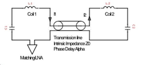
Fig.1 Building block of the “Less-for-More” coil: coils joined by
transmission line
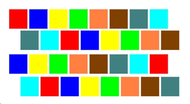
Fig. 2 Example of a 32-coil (4x8) “Less-for-More” array: coils with same
color are joined by transmission lines
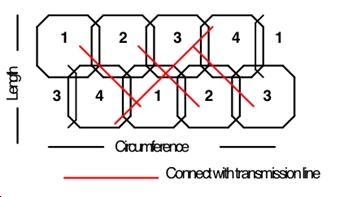
Fig. 3 Layout of a 4-channel 8-loop knee coil
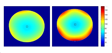
Fig. 4 Axial SNR maps of the 4ch 8-loop coil (left) and the 15-ch knee
coil (right)
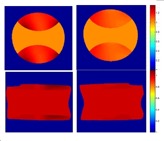
Fig. 5 Axial and sagittal g-factor maps of the 4-ch 8-loop coil (left)
and the 15-ch knee coil (right)