1604
Optimization of the degenerate birdcage transmit array coil for minimum coupling1Department of Electrical and Electronics Engineering, Bilkent University, Ankara, Turkey, 2National Magnetic Resonance Research Center (UMRAM), Bilkent University, Ankara, Turkey
Synopsis
This abstract introduced a methodology to minimize the magnetic coupling between non-adjacent channels in a degenerate birdcage transmit array coil (DBC) by optimizing some of its physical parameters. The method is based on minimization of the mutual-inductances normalized by the self-inductances. Optimum radius, length in the z-direction, the width of end-rings, and the width of rungs are found for a 3T shielded twelve-channel head DBC with capacitive decoupled loops. Finite element based simulation results confirmed the validity of the results.
Introduction
A degenerate birdcage coil (DBC) is a form of transmit array (TxArray) coil that can be used for local RF transmission as well as homogenous circularly-polarized field distribution in a large volume of interest. However, the coupling between the individual channels cause extra losses leading to an increase in power consumption and this has to be considered as a major issue in its design process. A variety of strategies tested to reduce the coil coupling including capacitive decoupling1, inductive decoupling2, transformers3, shared L/C elements4, and resonant structures5. In these methods, the physical parameters of coils were not considered as a degree of freedom for coupling reduction. We propose to minimize the ratio of mutual- to self-inductances of the individual channels of DBC by adjusting the physical parameters of the coil such as radius, length, end-ring width, and rung width in order to minimize the magnetic coupling2,6. As a sample design, a twelve-channel head DBC was considered and the simulation results confirmed the validity of the optimization results.Methods
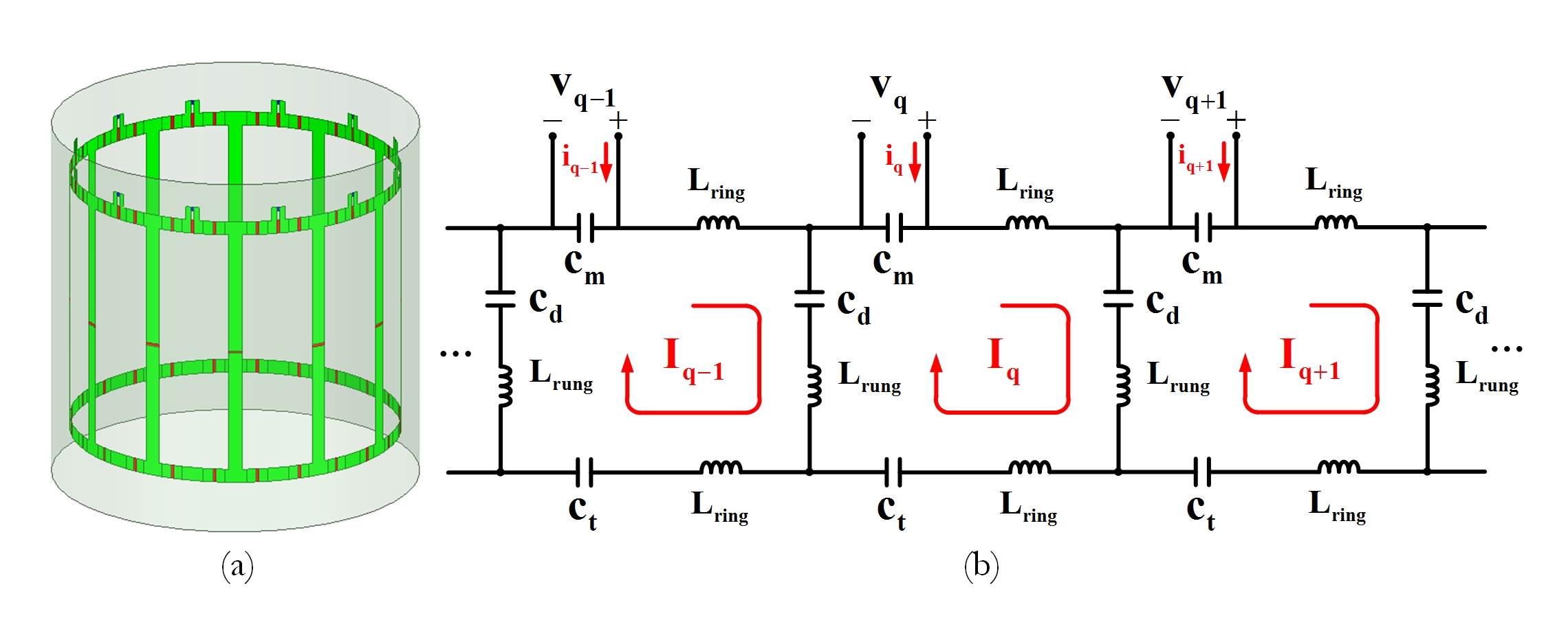
Fig.1 shows the equivalent circuit models of an unloaded twelve-channel DBC enclosed by an RF shield. The effects of all self- and mutual-inductances originating from the coil and its shield are considered in the equivalent circuit model. The effect of the load and other coil losses are not considered in this model.By applying the Kirchhoff mesh current method, the matrix equation is obtained as:
$$(j\omega_{0}K+\frac{1}{j\omega_{0}}H)I=\frac{1}{j\omega_{0}c_{m}}i$$
where $$$\omega_{0}$$$ denotes the angular frequency, I denotes the vector of the loop currents and i denotes the vector of the input currents. $$${\bf{H}}=\begin{bmatrix}H_{p,q} \end{bmatrix}_{12\times12}$$$ represents capacitance matrix where $$$H_{p,q}$$$ is defined as:
$$H_{p,q}=\begin{cases}\frac{2}{c_{d}}+\frac{1}{c_{m}}+\frac{1}{c_{t}} & q = p\\\frac{-1}{c_{d}} & q-p\equiv\pm1(mode 12)\\0 & elsewhere\end{cases}$$
$$${\bf{K}}=\begin{bmatrix}K_{p,q} \end{bmatrix}_{12\times12}$$$ is an inductance matrix where $$$K_{p,q}$$$ denotes the mutual-inductance between the qth and pth loops. $$$K_{q,q}$$$ denotes the self-inductance of the qth loop. Using Neumann formula8 K-matrix elements which are dependent only on the coil’s geometry, can be calculated.
If the non-diagonal elements of $$${\bf{A}}=j\omega_{0}({\bf{K}}-\frac{1}{\omega_{0}^{2}}{\bf{H}})$$$ are nulled, the coupling will be zero because the current of the nth loop depend only on the nth input current $$$(I_{n}={\bf{A}}_{n,n}i_{n})$$$. By using the capacitors, represented by the H-matrix, just those elements of A which satisfy the condition of $$$q-p=\pm1$$$ (in mod 12) can be made zero. It means that only the coupling between the adjacent channels can be canceled.
Therefore, in the optimization of the physical parameters of the coil, only the mutual inductor between non-adjacent elements are considered. The coil symmetry enables us to consider just the one channel of the coil. Therefore, the error function, EF, for channel 1 can be obtained by normalizing these values with respect to the self-inductance value as $$$EF=||\frac{1}{K_{1,1}}\begin{bmatrix}K_{1,3}&K_{1,4}&...&K_{1,11}\end{bmatrix}||_{2}$$$.
Results and discussion
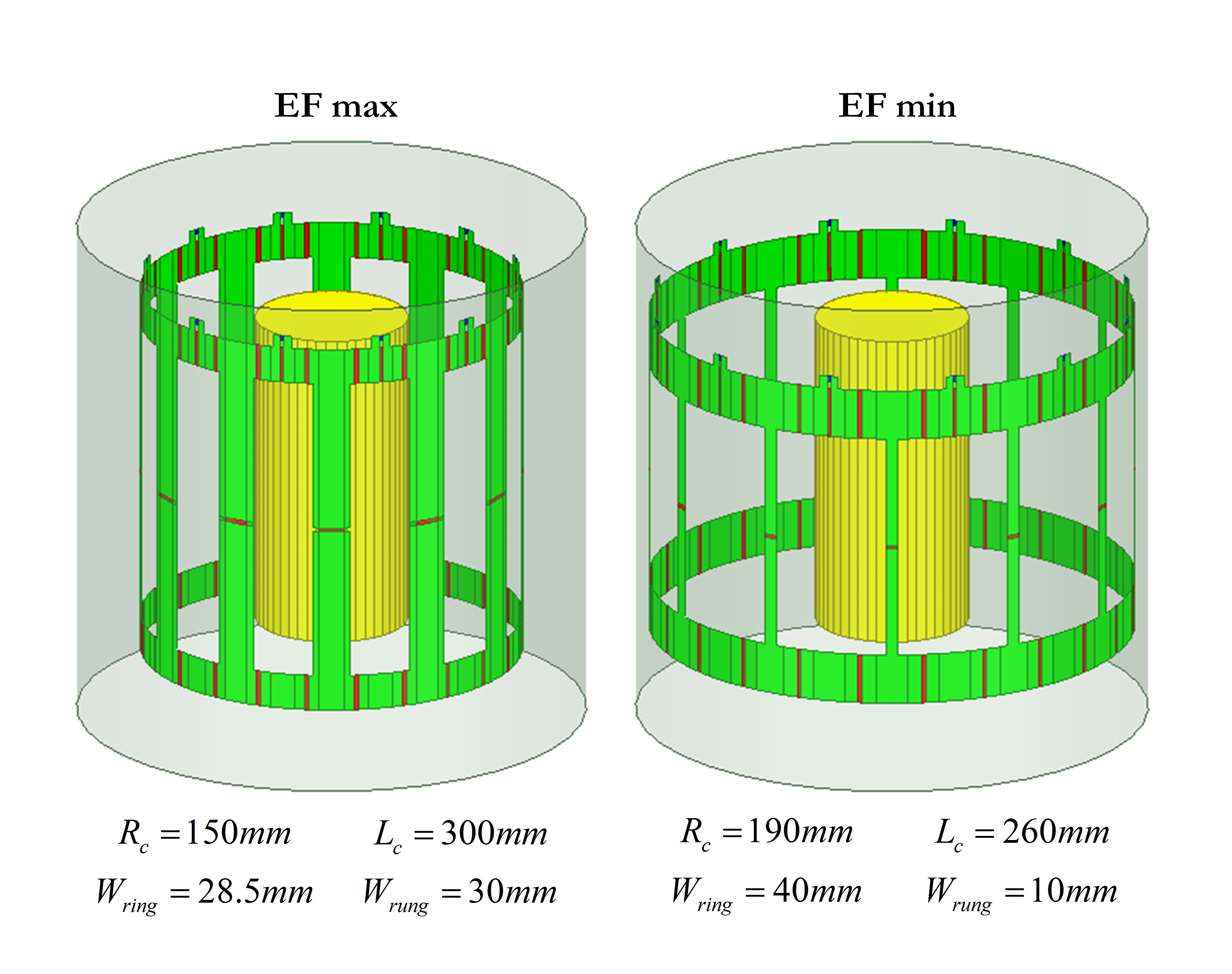
In order to appreciate the advantage of this optimization method, in a given range, the physical dimensions for a twelve-channel DBC with fix shield dimensions are calculated with two sets of design parameters that correspond to minimum and maximum error functions. The capacitor values for both of the DBCs (Fig.2) were found using the co-simulation strategy9 with the optimization criteria of minimum $$$\sum_{j=1}^{12}|S_{1j}|^{2}$$$.
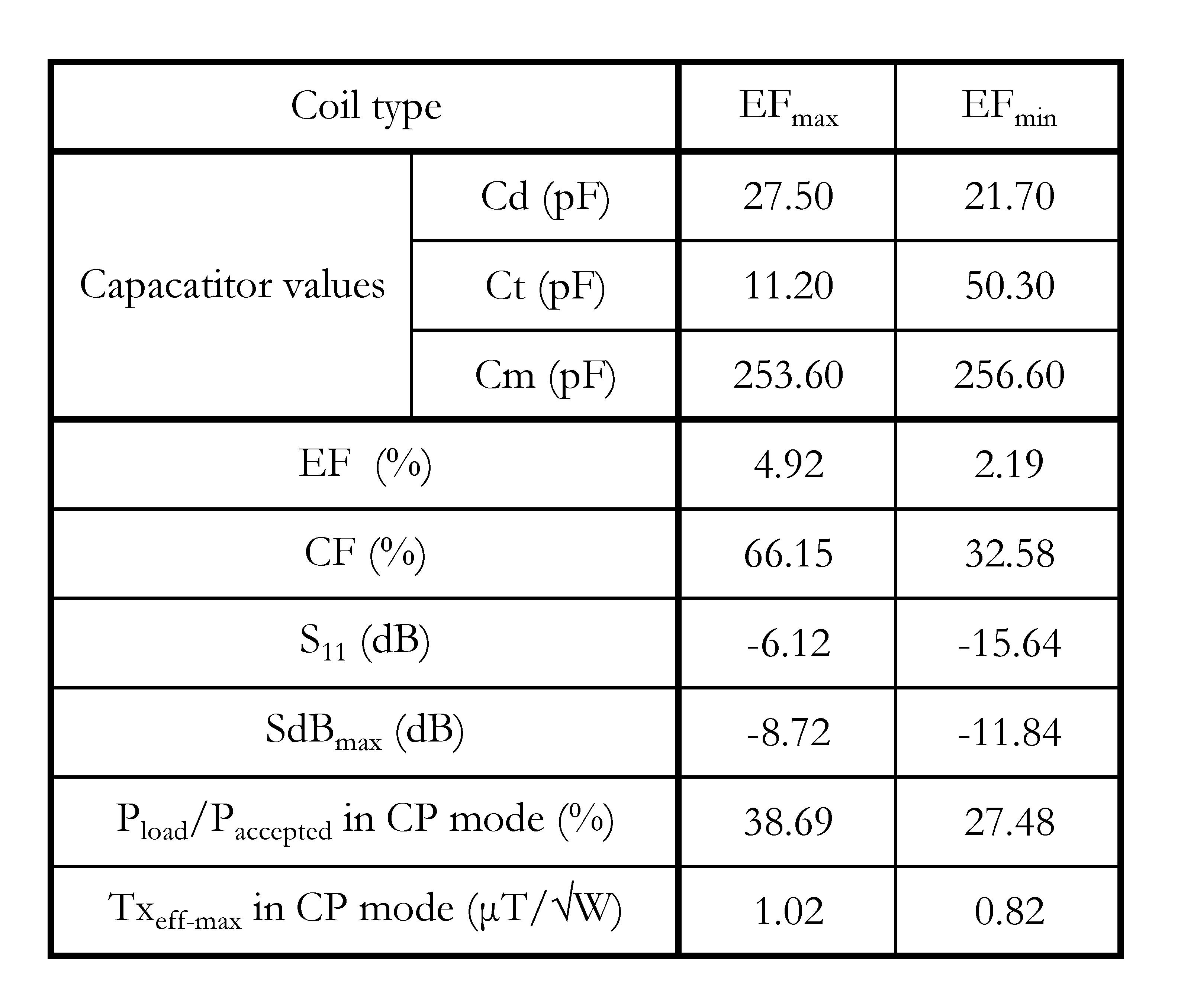
The optimal dimensions reveal that the coil radius and end-rings widths should increase while the coil length and the rungs widths should decrease. The performance of the coils at 3T (123.2MHz) in terms of the error function (EF), the cost function which is defined as $$$CF=\sum_{j=1}^{12}|S_{1j}|^{2}$$$, reflection coefficient (S11), maximum coupling (SdBmax), normalized power delivered to the load ($$$P_{load}\diagup{P_{accepted}}$$$), and transmit efficiency ($$$Tx_{eff}=B_1^+\diagup{\sqrt{P_{accepted}}}$$$) in circularly-polarized mode evaluated in Table 1.
Table 1 shows that optimizing the physical dimensions can improve the coupling level and as a result reduce CF. Decreasing $$$Tx_{eff}$$$ for the coil with the minimum EF in the CP mode showed that the close distance from the shield has a negative impact on the coil performance.
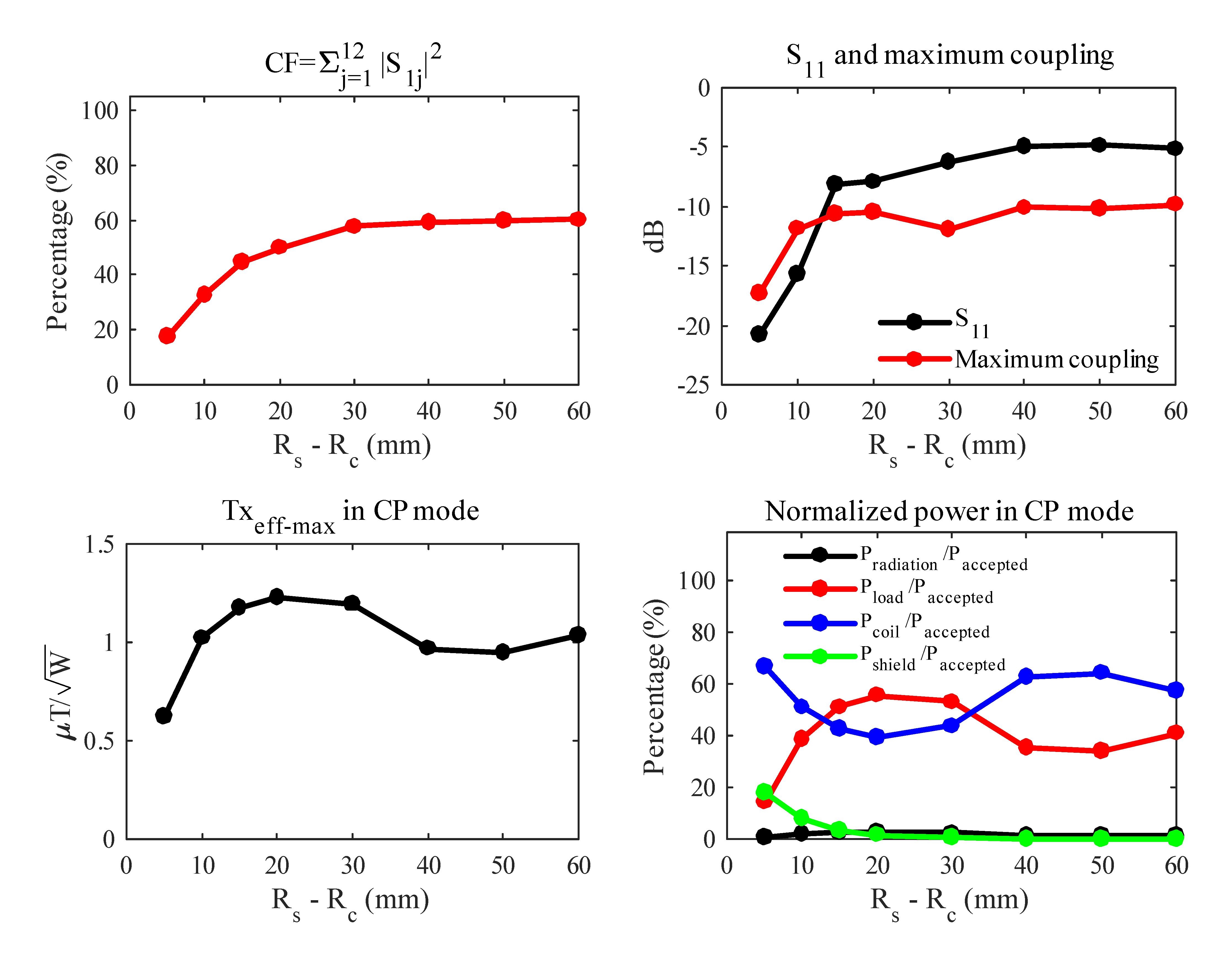
The performance of 8 twelve-channel DBC with different radiuses by minimization of the CF are assessed in Fig. 3. The capacitors were optimized to minimize CF. Decreasing Rs-Rc leading to a decrease in CF and maximum coupling. On the other hand, $$$Tx_{eff}$$$ in the CP mode is decreasing. Therefore the finding the optimal physical dimensions is a trade-off between the minimization of EF and increasing $$$R_{s}-R_{c}$$$. According to the results, $$$R_{c}$$$=180mm can be considered as the optimum value of the coil radius for the specific structure that we considered.
Conclusion
In this work, the physical parameters of a twelve-channel DBC optimized to minimize the magnetic coupling between its non-adjacent channels. The method showed that the coil radius and end-rings widths should increase while the coil length and the rungs widths should decrease. On the other hand, a sufficient distance from the shield should maintain to increase the transmission efficiency.Acknowledgements
No acknowledgement found.References
[1] Kazemivalipour E, Sadeghi Tarakameh A, Yilmaz U, Acikel V, Sen B, Atalar E. A 12-Channel Degenerate Birdcage Body Transmit Array Coil for 1.5T MRI Scanners. In Proceeding of the 26th Joint Annual Meeting ISMRM-ESMRMB, Paris, France 2018: Abstract 1708.
[2] Avdievich NI, Pfrommer A, Giapitzakis IA, Henning A. Analytical modeling provides new inside into complex mutual coupling between surface loops at ultra-high field, NMR Biomed. doi:10.1002/nbm.3759.
[3] Avdievich NI. Transceiver-phased arrays for human brain studies at 7 T. Appl Magn Reson 2011; 41:483–506.
[4] Wu B, Qu P, Wang C, Yuan J, Shen GX. Interconnecting L/C components for decoupling and its application to low-field open MRI array. Concepts Magn Reson Part B Magn Reson Eng 2007; 31B:116–126.
[5] Avdievich NI, Pan JW, Hetherington HP. Resonant inductive decoupling (RID) for transceiver arrays to compensate for both reactive and resistive components of the mutual impedance. NMR Biomed 2013; 26:1547–1554
[6] Heteren JG, Henkelman RM, Bronskill MJ. Equivalent circuit for coil-patient interactions in magnetic resonance imaging. Magn Reson Imaging 1987; 5:93 – 9.
[7] Lu DF, Joseph PM. A Technique of Double-Resonant Operation of 19F and 1H Quadrature Birdcage Coils, Magn Reson Med. 1991 May; 19(1):180-5.
[8] Grover WG. Inductance calculations: working formulas and tables, Courier Corporation, 2004.
[9] Kozlov M, Turner R. Fast MRI coil analysis based on 3-D electromagnetic and RF circuit co-simulation. Journal of Magnetic Resonance. 2009; 200(1):147–152.
Figures