1601
A High Duty Cycle, Multi-channel, RF Power Amplifier for High Resolution TRASE MRI1Department of Oncology, University of Alberta, Edmonton, AB, Canada, 2Department of Physics, Jagiellonian University, Krakow, Poland
Synopsis
A radiofrequency (RF) power amplifier is an essential component of any MRI system. Unfortunately, no commercial amplifier exists to fulfill the needs of the transmit array spatial encoding (TRASE) technique, requiring minimum 50% duty cycle, high output power 1 kW and independently controlled multi-channel capability. Hence a home-made dual channel RF power amplifier dedicated for TRASE at 0.22 T (9.27 MHz) was made using commercially available components. High spatial resolution one-dimensional TRASE was obtained with the power amplifier to demonstrate its capability. The results were compared with the commercial amplifiers, Analogic AN8110 and TOMCO BT00500, exceeding performance considering electronic noise and duty cycle.
Introduction
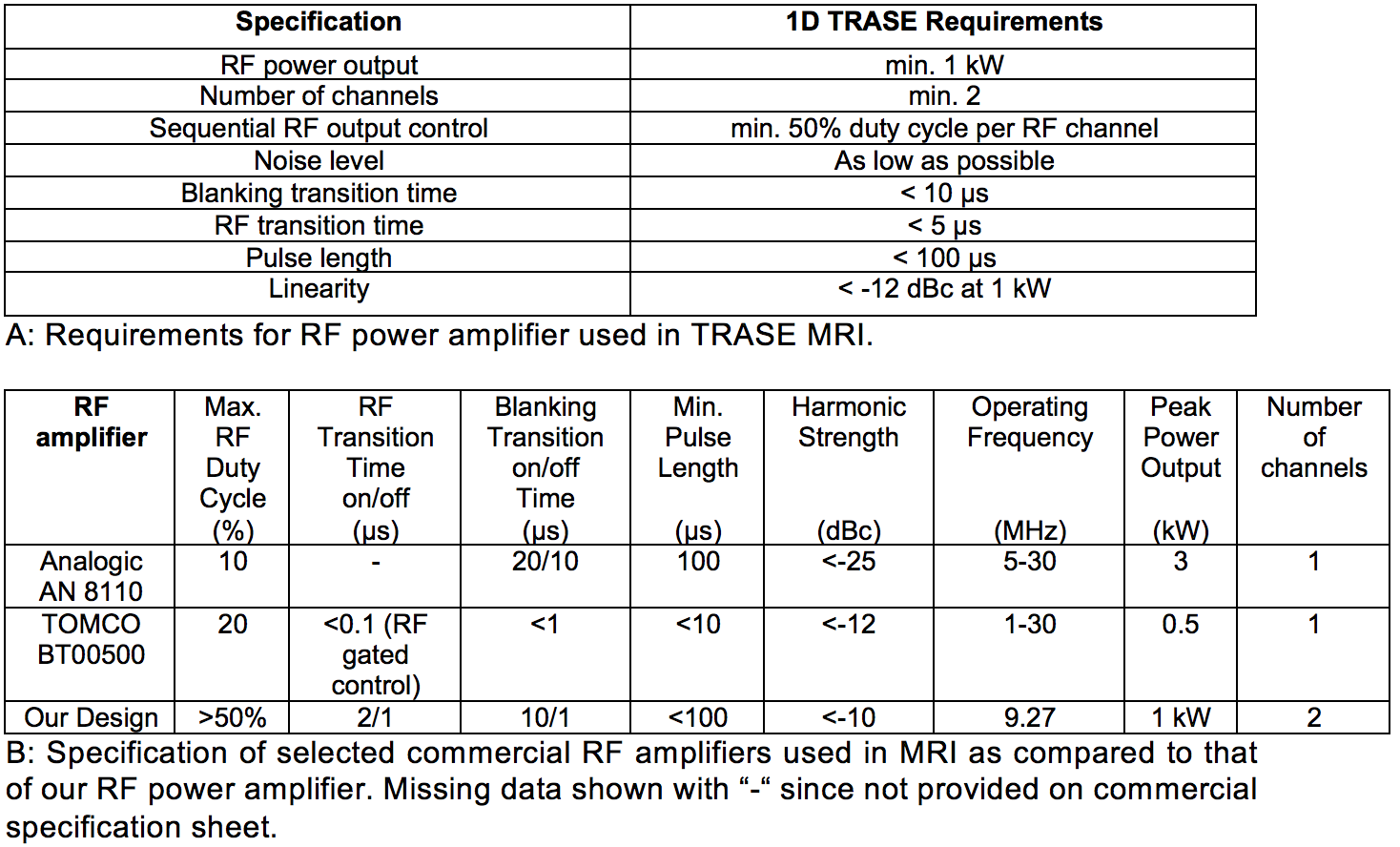
Standard MRI systems use gradients of the main magnetic Bo field to spatially encode signal for imaging1. Unfortunately, these systems are expensive, noisy and generate eddy currents, reducing imaging quality and even inducing nerve stimulation in patients2. An alternative encoding method called transmit array spatial encoding (TRASE) uses gradients of the phase of the radiofrequency (RF) field to spatially encode signal2-4. Therefore, TRASE removes the costly and problematic Bo gradient system, but it introduces new requirements on RF power amplifiers (Figure 1A). TRASE requires generation of echo trains using multiple, short, high power RF pulses to collect as many as possible k-space data points within T2 decay (30 ms for muscle tissue at 0.22 T). High resolution information is contained away from k-space origin, therefore, more spin echoes correspond to further k-space movement along the TRASE trajectory2-4. To enable high-resolution TRASE imaging, these requirements are not met by commercial RF power amplifiers3,4 (Figure 1A).
Commercial RF amplifiers are limited in timing of pulse, switching on/off and duty cycle, significantly reducing the number of acquired k-space points hence reducing spatial resolution (Figure 1B). Commercial RF amplifiers, such as Analogic AN8110 and TOMCO BT00500 BETA, have maximum 10% and 20% duty cycle, respectively, which is not sufficient for TRASE. To significantly increase spatial resolution at 0.22 T, we proposed a new RF amplifier (RFPA) dedicated for TRASE capable of a minimum 50% duty cycle, 2 μs RF transition on time (time between 0% and 90% of the RF output amplitude), 1 μs RF transition off time (time between 90% and 0% the RF output amplitude), 10 μs and 1 μs blanking transition on and off time (time between 50% of gating voltage and 50% of RF output amplitude), respectively and minimum 1 kW RF power output.
Design
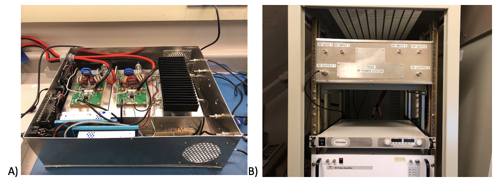
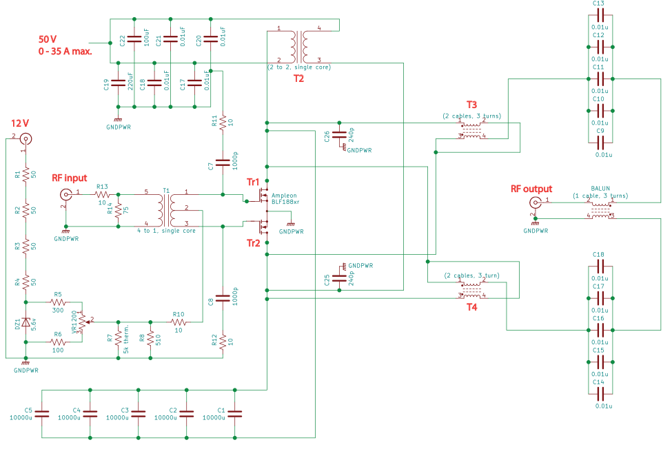
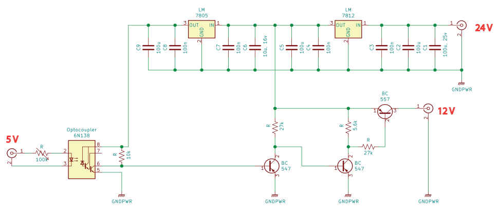
A multi-channel, high power RF amplifier was constructed using commercial components. The main amplifier unit has been adapted from amateur radio communication where continuous wave (CW) operation5 is common. We have adapted the design using an additional set of five, 10000 uF capacitors in parallel in the DC power circuit (Figure 4) and construction of a low power gating circuit allowing pulse operation of 1 kW RF power output (Figure 5). Additionally, we removed capacitors that introduced unnecessary RC delay in the biasing network of the RFPA to significantly speed up blanking and RF transition times. Two separate amplification channels are powered by a single, high power DC power supply (TDK Lambda GEN50-30, TDK-Lambda Americas Inc., USA). For each channel, a separate low power supply is used for the pre-amplifier (ZHL 1-2W+, Mini-Circuits, USA) and gating circuit. The amplifier was constructed and placed in rack of a 0.22 T MRI system (TMX, MRI-Tech Canada) as shown in Figure 2 for further performance testing. The detailed main amplification RFPA schematic is shown in Figure 4. The detail schematic for the gating circuit is shown in Figure 5.Results
We found that each channel of the amplifier can deliver higher than 50% duty cycle, 100 μs or shorter pulse length, less than 10 μs between pulses and is capable of 1 kW RF output. The RF amplifier produces 42% lower electronic noise than commercial RF amplifiers. 1D TRASE was acquired with both our RF power amplifier as well as Analogic AN8110 and TOMCO BT00500 BETA amplifiers for comparison. The high duty cycle and fast switching times of our RF amplifier enabled 4-fold increase in spatial resolution using TRASE relative to commercial RF amplifiers. High resolution one-dimensional (projection) TRASE will be presented.
Discussion
Lower noise figure achieved by the reduced number of amplification stages (Friis’ Formula) allowed higher SNR to be obtained. Beside TRASE, the amplifier may also be used in standard MRI systems. In the next step, we will construct a four channel RF power amplifier which will enable high resolution 2D TRASE imaging.
Conclusion
Our RF power amplifier has proved its capability for use in standard MRI and TRASE MRI. It showed superior performance in most of the specifications when compared to commercial RF power amplifiers. The RF power amplifier removes a major limitation of duty cycle and timing present in commercial RF power amplifiers making possible future sub-millimeter in-vivo spatial resolution in TRASE MRI.Acknowledgements
We thank Curtis Osinchuk and Lance Spiridon, Cross Cancer Institute, Edmonton, AB, CA for constructing enclosure for the RF amplifier and Vyacheslav Volotovskyy, Cross Cancer Institute, Edmonton, AB, CA for technical support.References
1. Brown RW, Cheng YN, Haacke EM, Thompson MR, and Venkatesan R. Magnetic Resonance Imaging: Physical Principles and Sequence Design. Wiley Blackwell. Second Edition. (2014).
2. Sharp JC, King SB, Deng Q, Volotovskyy V, and Tomanek B. High-resolution MRI encoding using radiofrequency phase gradients. NMR in Biomedicine, 26: 1602-1607 (2013).
3. Deng Q, King SB, Volotovskyy V, Tomanek B, and Sharp JC. B1 transmit phase gradient coil for single-axis TRASE RF encoding. Magnetic Resonance Imaging, 31: 891-899 (2013).
4. Sharp JC and King SB. MRI Using Radiofrequency Magnetic Field Phase Gradients. Magnetic Resonance in Medicine, 63: 151-161 (2010).
5. Amateur Ratio Station W6PQL. www.w6pql.com.
Figures