1599
A Frequency Selective RF Shield for MR Guided Thermal Therapies at 3T1Radiology and Imaging Sciences, University of Utah, Salt Lake City, UT, United States, 2NeoTherma Oncology Inc., Wichita, KS, United States
Synopsis
A proof of concept, a passive frequency selective RF shield was designed and constructed to block a single frequency (13.56 MHz) from passing through the shield. S21 and phantom SNR measurements demonstrate near transparency to the 123 MHz imaging frequency.
Introduction
With the ability of MRI to measure temperature [1], more MRI research is focused on MR guided thermal therapy interventional procedures, such as High-Intensity Focused Ultrasound (HIFU) and Radio Frequency (RF) heating and ablation. These interventions typically use power at frequencies that are very different than the imaging frequency. If there is any significant power used in the MRI scanner for these therapies, the susceptibility and compatibility is not straightforward with MR vendor system hardware.
In some high-power interventional studies an RF shield could protect the vendor electronics from radiated energy. However, shielding power at the interventional frequency typically attenuates the imaging frequency as well, disallowing use of the system body coil for imaging. Separate transmit and receive hardware would be required to operate in the thermal therapy environment, inside the shield.
This work describes the development of an RF shield to protect vendor hardware from the thermal therapy frequency (13.56 MHz) while being transparent to the imaging frequency (123MHz) for image guidance.
Methods
The frequency-selective shield was implemented on a cardboard cylinder with a 31cm diameter and 41cm length. 32 strips of copper tape, 2.54cm width and 41cm in length, were positioned around the cylinder with gaps of approximately 0.6cm as shown in Figure 1.
The shield was first constructed using the series resonant circuit of Figure 2A to span the gaps between copper strips. This circuit allowed the 13.56MHz eddy currents to flow freely between copper strips as they would in a solid copper shield. However, S21 measurements across the surface of the shield resulted in more attenuation of the 123MHz imaging frequency than was desired. The filter circuits were then modified (Figure 2B) to include a parallel resonant trap to block 123MHz eddy currents from flowing in the shield.
To minimize the number of components and associated costs, Qucs [2] simulations (Figure 2C) were performed to determine components with standard off-the-shelf values. For the circuits in Figure 2, the components C1 = 2200pF and L1 = 63.6nH formed the 13.56 series resonance. The addition of C2 = 27pF formed the parallel resonant blocking circuit. For this modified circuit, the inductor L1 was adjusted to 63nH for best attenuation at 123MHz. Capacitors were non-magnetic (Knowles Syfer), and the inductors were variable (Coilcraft).
To determine how many filter circuits would be required along each gap, four test conditions were established consisting of 1, 3, 5, and 7 filter circuits soldered between strips at evenly-spaced intervals along each gap of the shield. Shielding effectiveness was assessed for each test condition with S21 measurements between two large test loops [3] that were approximately 16.5cm in diameter and positioned on opposite sides of the shield surface.
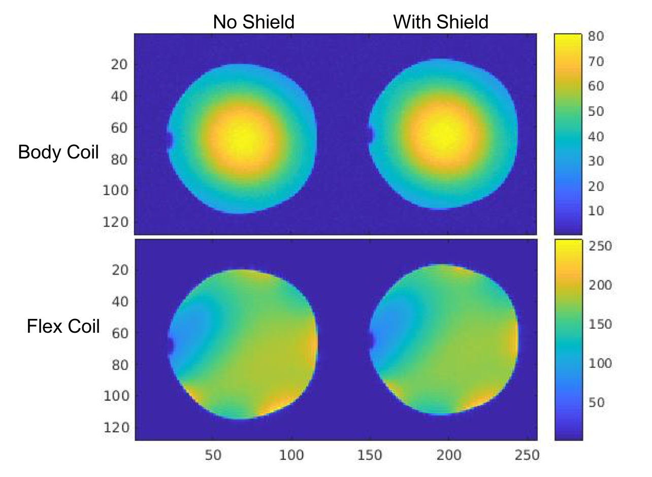
Finally, using the modified filter circuit (Figure 2B), imaging experiments were performed using the Body coil only and with the Body/Siemens 4-chFlex array to asses phantom SNR with and without the shield in place. The phantom was a 15cm diameter plastic bottle filled with CuSo4 and NaCl solution. SNR maps were generated for each imaging study using the Kellmen method [4].
Results
The prototype shield for this work is shown in Figure 1 with 7 filter circuits across each gap. S21 measurements of the filter circuits were very similar to the Qucs predictions in Figure 2C.
The shield S21 measurements as presented in Table 1 indicate that 13.56MHz shielding was essentially equal for both filter circuits, but the addition of C2 improved the 123MHz transparency of the shield significantly.
Imaging study results are presented in Figure 3. Little difference can be observed in the body coil images and only subtle differences in the Flex coil images can be seen. It appears that the shield does attenuate the transmit signal slightly as the transmit reference voltage changed from 304 volts without the shield to 313 volts with the phantom inside the shield.
Discussion
The shield developed in this work provided the desired effect of shielding the thermal therapy frequency of 13.56MHz by 17-20 dB, while passing the imaging frequency of 123MHz with less than 0.5 dB attenuation.
Being a feasibility study, many of the shield parameters have not been optimized (i.e., copper strip length, width, and spacing, and filter circuit effectiveness and placement). Future work will optimize the performance of this shielding concept.
Conclusion
This study demonstrates that an RF shield can be constructed to provide significant shielding at a particular frequency of concern to prevent coupling into vendor system hardware, while being nearly transparent to the MR imaging frequency for MR guided therapy purposes.Acknowledgements
This work was sponsored by NeoTherma Oncology, Inc.References
1. Parker DL, Smith V, Sheldon P, Crooks LE, Fussell L. Temperature distribution measurements in two-dimensional NMR imaging. Med Phys 1983;10(3):321-5.2.
2. http://qucs.sourceforge.net/3.
3. Hoult DI. The Principle of Reciprocity in Signal Srength Calculations: A Mathematical Guide. Concepts Magn Reson A 2000;12:173-187.4.
4. Kellman P, McVeigh ER. Image Reconstruction in SNR Units: A Geneal Method for SNR Measurement. Magn Reson Med. 2005 December; 54(6):1439-1447.
Figures
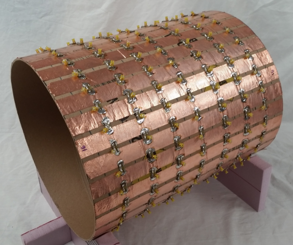
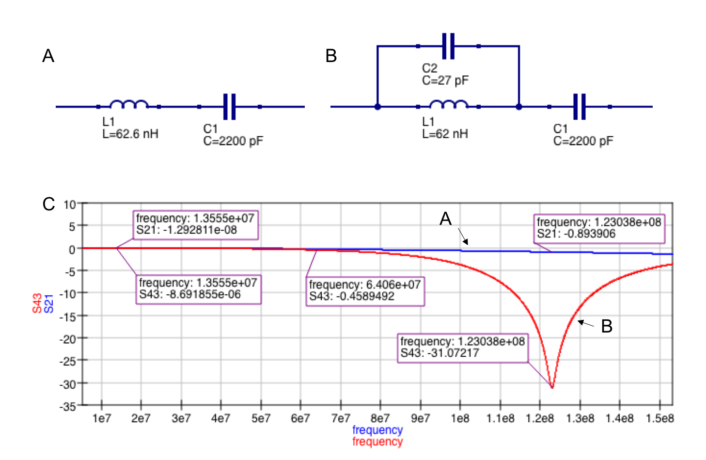
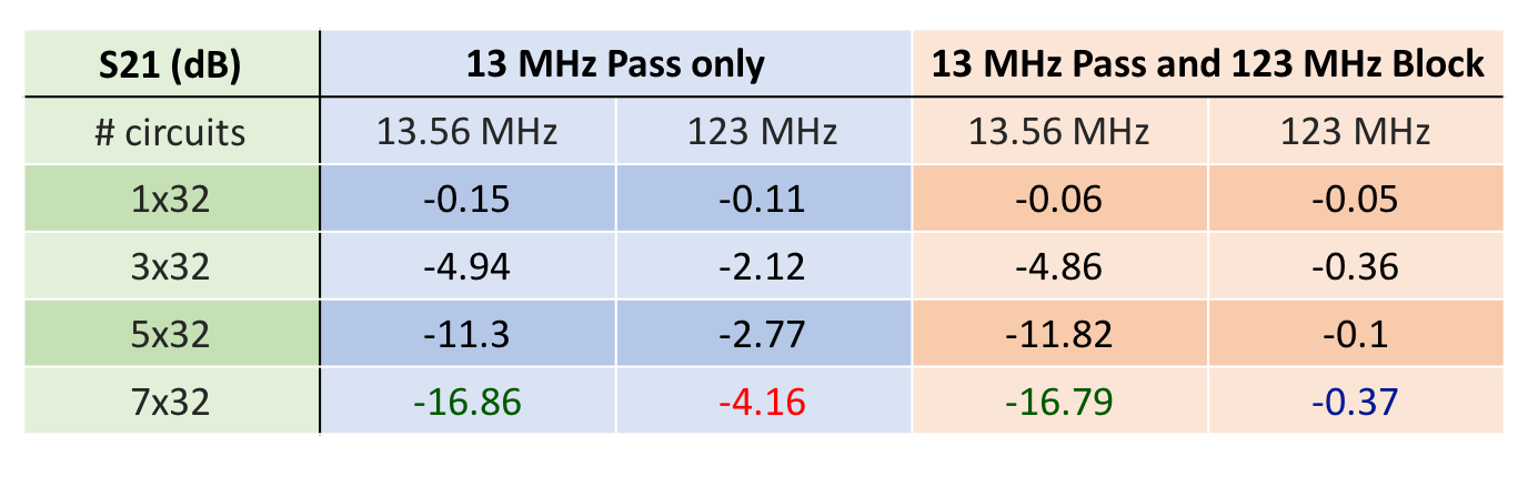
Table 1: Frequency selective Shield S21 Measurements
Average S21 measurements for 2 approximately 16.5 cm diameter test loops placed on opposite sides of the shield surface. One loop was inside the shield and one loop was outside the shield. As expected, the shield effectiveness improves as more shunt circuits are added to span the gap between copper strips. The 123 MHz blocking circuit significantly improves the transparency of the shield at the imaging frequency.