1598
MR thermometry guided RF hyperthermia in the head and neck region – does the new MRcollar affect the imaging?1Department of Radiation Oncology, Erasmus MC - Cancer Institute, Rotterdam, Netherlands, 2Faculty of Biomedical Engineering, Czech Technical University in Prague, Prague, Czech Republic, 3Department of Radiology, Erasmus MC, Rotterdam, Netherlands, 4Department of Electrical Engineering, Technical University of Eindhoven, Eindhoven, Netherlands
Synopsis
Clinical studies established that adjuvant effect of mild hyperthermia can be improved by increasing thermal dose, which can be improved by online 3D dosimetry. To take advantage of MR thermometry, we developed an MR compatible head and neck RF hyperthermia applicator prototype for the head and neck region: the MRcollar. To establish the impact of the MRcollar on image quality, we imaged B1+ map and calculated the Signal-to-Noise Ratio when the body coil was used.
Introduction
Mild radiofrequency (RF) hyperthermia as adjuvant to radiotherapy increases the likelihood of complete response to head and neck (H&N) cancers [1]. At the Erasmus MC, the Hypercollar3D applicator is being used to treat H&N tumors with RF hyperthermia [2]. The thermal dose effect relationship suggests that clinical outcome can be improved by increasing thermal dose [3]. Given the high thermoregulation response of H&N tissues, close monitoring of both the temperature distribution in the target region and monitoring of hotspots in normal tissues is a prerequisite for optimizing the tumor heating. Temperature monitoring during hyperthermia by temperature probes invasively placed is challenging and risky, and therefore often not used. Non-invasive temperature monitoring using magnetic resonance (MR) temperature imaging holds great promise to enable achieving the full clinical potential of hyperthermia. Hence, we developed an MR compatible clinical H&N RF hyperthermia applicator prototype: the “MRcollar”. Here, we studied the impact of the MRcollar on B1+ (flip angle maps) and the Signal-to-Noise Ratio (SNR) when imaging using the body coil.Materials and Methods:
The MRcollar contains two moon-shaped shells, which are placed around the H&N and contains six antenna modules in a 2x3 arrangement. Every module contains a printed Yagi-Uda antenna submerged in water and operating at 433.92 MHz. To improve coupling of electromagnetic waves; a water bolus is placed between the antenna modules and the skin. Two phantoms are used in the evaluation; “Phantom 1”: a cylindrical phantom provided by the vendor (T1: 108 ms,T2: 96 ms), “Phantom 2”: an anthropomorphic homogenous H&N phantom (T1: 820 ms; T2: 37 ms ). In Figure 1, Phantom 2 is placed inside the MRcollar and into the scanner bore (1.5T GE MR450w, GE Healthcare, Waukesha, WI).
Three different setups were used;
- Setup 1: without the MRcollar present in the scanner but at an equal reference height.
- Setup 2: MRcollar present without an inner water bolus; to investigate the impact of the metallic structures (such as connectors and copper antenna parts).
- Setup 3: MRcollar present and inner water bolus applied between the shells and the phantom.
SNR scans: two SPGR acquisitions (with and without excitation RF pulse) with the following parameters: slice thickness 2 mm, slice spacing 22 mm, 10 slices, FOV 500x500 mm2, matrix 256x256, TR/TE 75/4.5 ms, NEX 1. Flip angles were chosen according to Ernst angle relation; 60° for Phantom 1 and 24° for Phantom 2.
B1+ maps: Bloch-Siegert sequence with slice thickness 10 mm, slice spacing 22 mm, 10 slices, FOV 500x500 mm2, matrix 128x128, TR/TE 19/13.4 ms, NEX 1, flip angle 30°. Transmit gain and shimming were kept constant across scans.
A region of interest (ROI) was defined to calculate the mean SNR and flip angle values. The same ROI was used for both phantoms and the change in SNR for Setup 2 and 3 is given relative to Setup 1.
Results
Figure 2 shows the example magnitude images from Setup 1 and 3 for both phantoms. There is no qualitative drop in image quality.
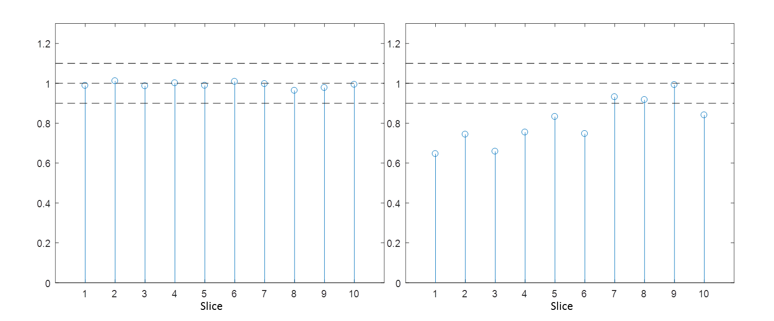
Figure 3 and 4 show the normalized change in the SNR for Phantom 1 and Phantom 2, respectively. The presence of the MRcollar without the water bolus did not alter SNR for both setups. On the other hand, inclusion of water bolus caused a reduction in SNR, especially in the first three slices.
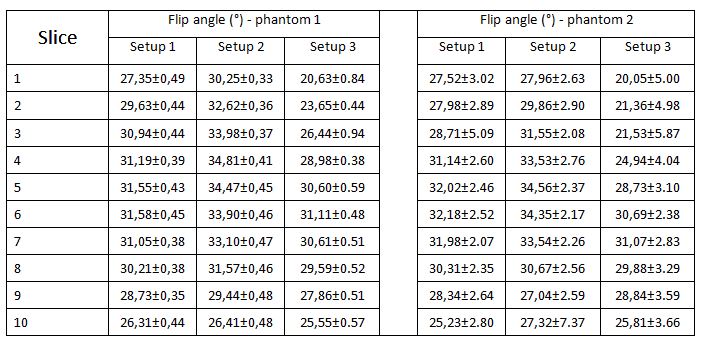
Table 1 presents the mean flip angle values and the standard deviation in each setup. Inclusion of MRcollar increased the flip angle values but homogeneity was unaffected. In Setup 3, a smaller flip angle than the prescribed was received by the first three slices. In the isocenter, nominal flip angle was achieved in both cases.
Discussion and Conclusion
Our work shows that the metallic parts contained in the antenna structures have a minimal effect on the image quality in the ROI: the SNR values stayed in the range of Setup 1 and only a small change in over flipping direction was observed. The low standard deviation in the SNR results confirms the homogeneity. This confirms earlier experimental findings that the Yagi-Uda antenna array does not affect MRI scans [4]. The effect of the water bolus was found much stronger than the metallic parts of the device: the signal level dropped due to the under flipping of the magnetization vector especially in the first three slices. This drop can be explained by energy losses in the water bolus. However, since homogeneity of the flip angle maps were not affected, the loss in SNR can be easily be countered by a proper B1 shimming and/or an adjustment of the transmit gain.Acknowledgements
This study was supported by the Dutch Cancer Society, grant EMCR2012-5472. Authors would like to thank Maarten Zwart for his contribution in device, phantom and experimental preparations.References
[1] Datta NR, Rogers S, Ordóñez SG, Puric E, Bodis S. Hyperthermia and radiotherapy in the management of head and neck cancers: A systematic review and meta-analysis. International Journal of Hyperthermia. 2016 Jan 2;32(1):31-40.
[2] Paulides MM, Rijnen Z, Togni P, Verhaart RF, Drizdal T, De Jong D, Franckena M, Verduijn GM, Van Rhoon GC. Clinical introduction of novel microwave hyperthermia technology: the HYPERcollar3D applicator for head and neck hyperthermia. InAntennas and Propagation (EuCAP), 2015 9th European Conference on 2015 May 13 (pp. 1-4). IEEE.
[3] Franckena M, Fatehi D, de Bruijne M, Canters RA, van Norden Y, Mens JW, van Rhoon GC, Van Der Zee J. Hyperthermia dose-effect relationship in 420 patients with cervical cancer treated with combined radiotherapy and hyperthermia. European Journal of Cancer. 2009 Jul 1;45(11):1969-78.
[4] Paulides MM, Mestrom RM, Salim G, Adela BB, Numan WC, Drizdal T, Yeo DT, Smolders AB. A printed Yagi–Uda antenna for application in magnetic resonance thermometry guided microwave hyperthermia applicators. Physics in Medicine & Biology. 2017 Feb 8;62(5):1831.
Figures
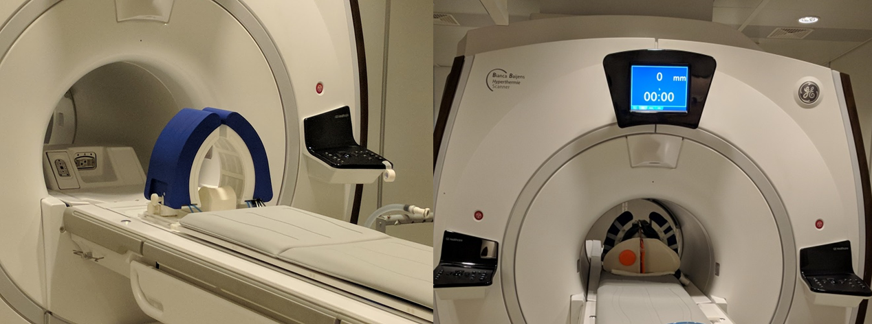
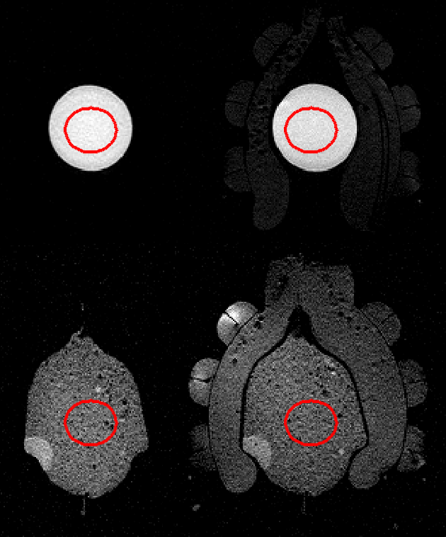
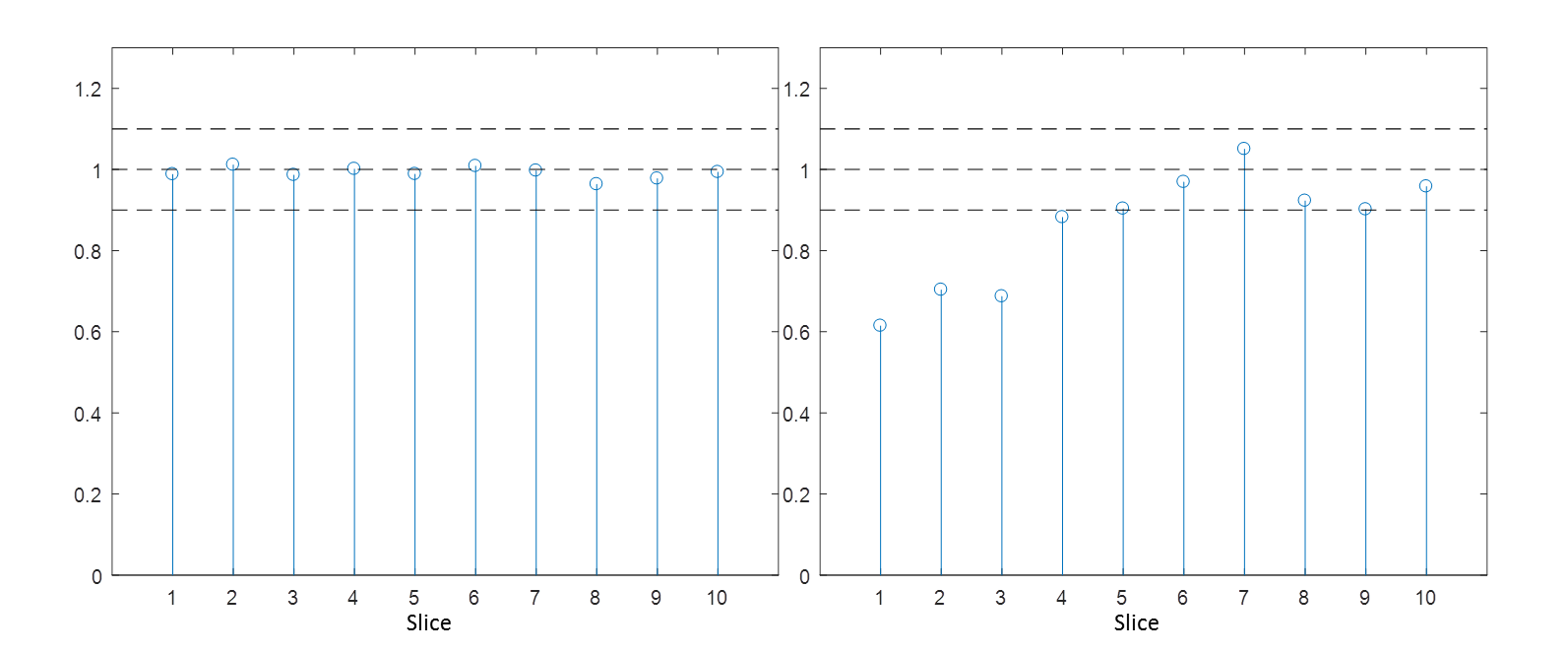
Figure 3. Relative change SNR compared to Setup 1 for Phantom 1 (a) Setup 2 (b) Setup 3. Dashed lines indicate +10% cutoffs.