1589
Circumventing Radiation Beam and RF-Coil Collisions in a Rotating B0 Linac-MR Hybrid using a Three-channel Array1Medical Physics, Cross Cancer Institute, Edmonton, AB, Canada, 2Oncology, Division of Medical Physics, University of Alberta, Edmonton, AB, Canada
Synopsis
Hybrid radiation therapy and magnetic resonance imaging (MRI) systems are providing new options for cancer therapy. In our design the B0 rotates on a gantry along with the linear accelerator (linac) for treatment delivery. This introduces new challenges to RF-coil design as the plane of MR precession changes depending on gantry angle. Our three channel array is appropriate for the head and consists of two butterfly coils and a circular loop. The array provides equal SNR at all gantry angles while allowing a radiation window to avoid collisions between the radiation beam and the RF-coils.
Introduction
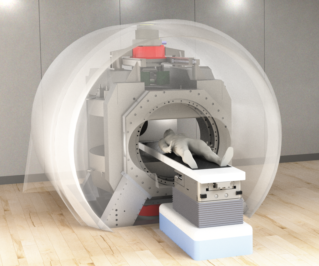
Magnetic resonance provides soft-tissue imaging superior to that of the traditional x-ray imaging typically incorporated with medical linear accelerators (linacs). The linac delivers an external radiation beam from various angles around the patient. In our linac-MR prototype (Fig. 1) the MR scanner (modified ParaMed MrOpen, 0.5 tesla) also rotates on a gantry with the linac, and the static B0 field of the magnet is always parallel to the radiation beam1. The rotation of B0 presents a challenge for RF coil design because there will likely be gantry orientations in which the received signal will be ≅ 0 (e.g., when B0 ⊥ to a surface coil). When delivering radiation, operator access to the vault is not permitted, and therefore RF coils cannot be readjusted to optimize reception for each gantry angle. Coils should also remain outside the beam at all angles because delivering radiation through them increases skin dose to unacceptable levels2.Methods
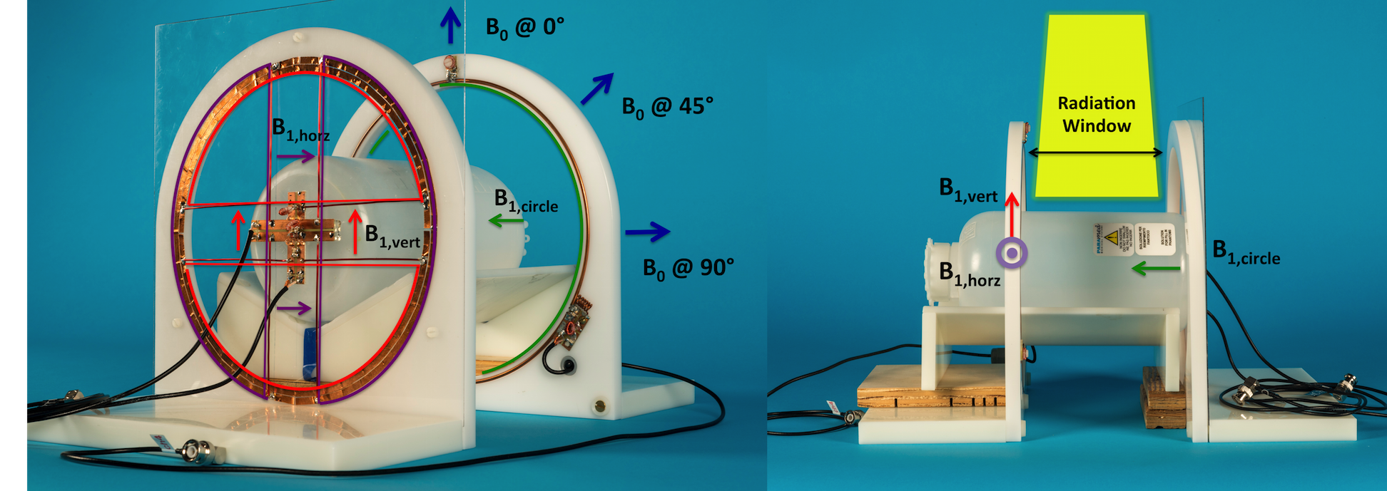
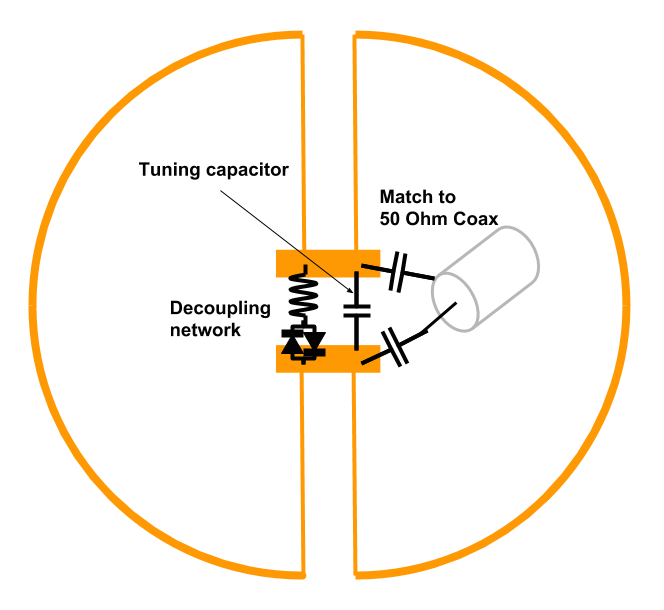
In our rotating-field scanner, RF coils must be sensitive to magnetization along all three perpendicular axes for optimal and constant sensitivity at all gantry angles. The three-channel receive-only head array, includes a circular loop that couples to the patient axis which is ⊥ to B0 at all times. Two butterfly coils3 couple to the horizontal and vertical axes perpendicular to the patient axis (Fig. 2). The circular loop is a copper ring (3.2 mm wide, 24 cm ⌀) with tuning provided by three capacitors distributed in series (2x 82 pF, 1x 75 pF). Each butterfly coil consists of two D’s (24 cm ⌀) of copper tape (5 mm wide) connected with straight copper wire (1.4 mm ⌀) and the butterfly mode is tuned to the Larmor frequency (20.56 MHz) with capacitors (150 pF and 60 pF in parallel) as shown in Figure 3. Each coil is matched to 50 Ω and includes passive detuning networks consisting of toroidal inductors (380 nH) and crossed-diodes (1N4148 diodes) in parallel with the tuning capacitors.
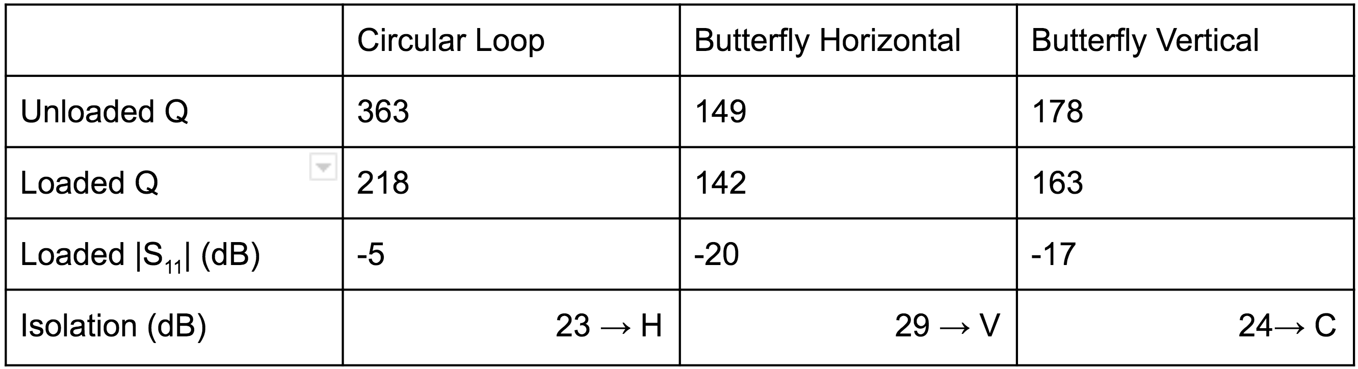
Bench measurements of quality factor (Q), matching and isolation were performed on a Rohde and Schwarz ZVL3 VNA using low (-15 dBm) output power to avoid activating the passive traps.The three channels were each connected to a MAR 8+ preamplifier (Mini Circuits), providing 31 dB gain and a 3 dB noise figure. Bench measurements and imaging were performed using a 2-litre aqueous cylindrical phantom (11.5 cm in diameter and 21 cm in length), containing 55 mM NaCl and 5 mM NiCl2.
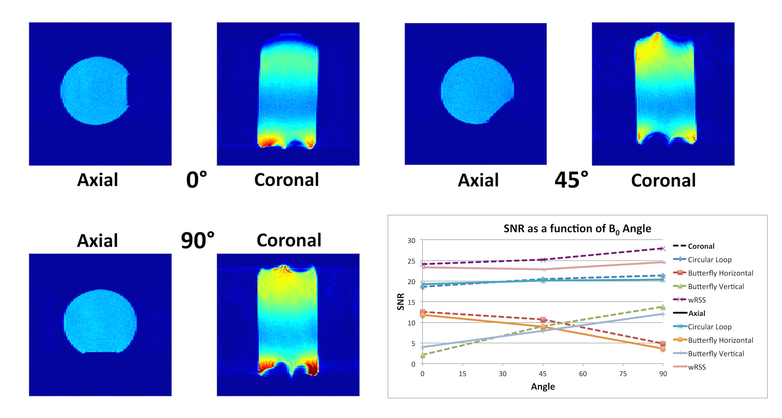
Gradient echo images (single slice, 5 mm thick, 35 cm FOV, flip angle 80 deg, TE 12 ms, TR 140 ms) and noise scans were acquired with B0 at 0° (vertical), 45°, and 90° (horizontal) with the phantom positioned at the isocenter (Fig. 2). The circular loop was positioned 18 cm from the two butterfly coils. This 18 cm gap represents the maximum window required for a treatment beam for the head. The iso-center along the patient axis was 8 cm from the butterfly arrays and 10 cm from the circular loop as the circular loop is expected to have greater penetration. At each angle one axial slice (parallel to B0 and perpendicular to patient couch) and one coronal slice (parallel to couch) were acquired and the raw data for each channel was saved and reconstructed individually in MATLAB. For each angle and slice the individual images were combined into a single SNR image with weighted root sum of squares (wRSS) combination4. SNR for each channel was evaluated as the ratio of the mean signal in a 4.5⨉8.5 cm2 ROI at the center of the phantom and the standard deviation of the noise image.
Results
Bench measurement results are shown in Table 1, showing appropriate coil sensitivity and coupling for all coils and coil pairs. Image analysis shows uniform SNR is achieved at all angles (Fig. 4). As expected, the SNR of one butterfly channel complements the other, allowing the three-channel array to maintain approximately the same combined SNR at all gantry angles. The highest noise correlation was between the two butterfly coils (0.32).Conclusion
The 3-channel array demonstrates that three perpendicular channels can be combined to achieve uniform image quality independent of B0 orientation. Specifically SNR is independent of gantry angle, which is ideal for the rotating B0 Linac-MR Hybrid.Acknowledgements
We thank Paramed for technical support and Emmanuel Blosser and Cory Lambert for expertise with the Linac-MR. Mechanical components were built by Lance Spiridon and Curtis Osinchuk. We also thank Dr. Satyapal Rathee and Dr. Andrei Ghila for discussions on the collision of the radiation beam and RF-coils.
We acknowledge funding from Natural Sciences and Engineering Research Council (NSERC), Alberta Cancer Foundation (ACF), and Alberta Innovates Health Solutions (AIHS). Special thanks to Alberta Health Services (AHS) for their continued support of the Alberta Linac-MR project.
References
- Fallone, B. G. (2014). The Rotating Biplanar Linac–Magnetic Resonance Imaging System. Seminars in Radiation Oncology, 24(3), 200–202. http://doi.org/10.1016/J.SEMRADONC.2014.02.011
- Ghila, A., Fallone, B. G., & Rathee, S. (2016). Influence of standard RF coil materials on surface and buildup dose from a 6 MV photon beam in magnetic field. Medical Physics, 43(11)
- Schnall, M. D., Summers, J. J., Haselgrove, J. C., Gyulai, L., McLaughlin, A., Chance, B., & Leigh Jr., J. S. (1986). Elimination of Inductive Coupling Through the Use of Butterfly Coils. Proceedings of the International Society for Magnetic Resonance in Medicine, 1986(S1), 45–46. Retrieved from https://onlinelibrary.wiley.com/doi/epdf/10.1002/mrmp.22419860101
- Roemer, P. B., Edelstein, W. A., Hayes, C. E., Souza, S. P., & Mueller, O. M. (1990). The NMR phased array. Magnetic Resonance in Medicine, 16(2), 192–225. http://doi.org/10.1002/mrm.1910160203
Figures