1583
A highly-miniaturized inverted cable trap1Institute of Imaging Science, Vanderbilt University, Nashville, TN, United States, 2Radiology and Radiological Science, Vanderbilt University, Nashville, TN, United States
Synopsis
Cable traps are commonly used for RF coils to suppress the common-mode current flowing on the outer conductor of coaxial cables. In massive-element array coils, conventional cable traps become cumbersome and not easy to assemble due to the limited space. In this work, we propose a novel circuit component called an “inverted cable trap”, which uses the outer conductor of a coaxial cable to form a capacitor rather than an inductor and which can be highly miniaturized. This inverted trap suppresses common-mode signals by up to -23 dB at 300 MHz which makes it valuable for operations at 7T.
Purpose
Balanced-to-unbalanced (balun) circuits are commonly used with RF coils to suppress the common-mode current flowing on the outer conductor of coaxial cables, which thereby avoids couplings between the coil and the environment and reduces potential hazards of burns to people. Several balun circuits have previously been developed for RF coils, including cable traps 1, floating traps 2, bridges 3 and lattice circuits 4. The cable trap is the most widely used solution because it is easy to build in practice and exhibits high suppression levels. When applied to massive-element array coils, however, conventional cable traps become cumbersome and are not easy to assemble in a limited space. This is partly because the coax is wound as a large solenoid, and partly because of the need of an additional outer shielding to avoid cross-talk with the environment. However, if the coax outer conductor is used to form a capacitor rather than an inductor i.e., an “inverted cable trap”, it can be highly miniaturized. In this work, we investigated the possibility of building such an inverted cable trap and evaluated its performance.Methods
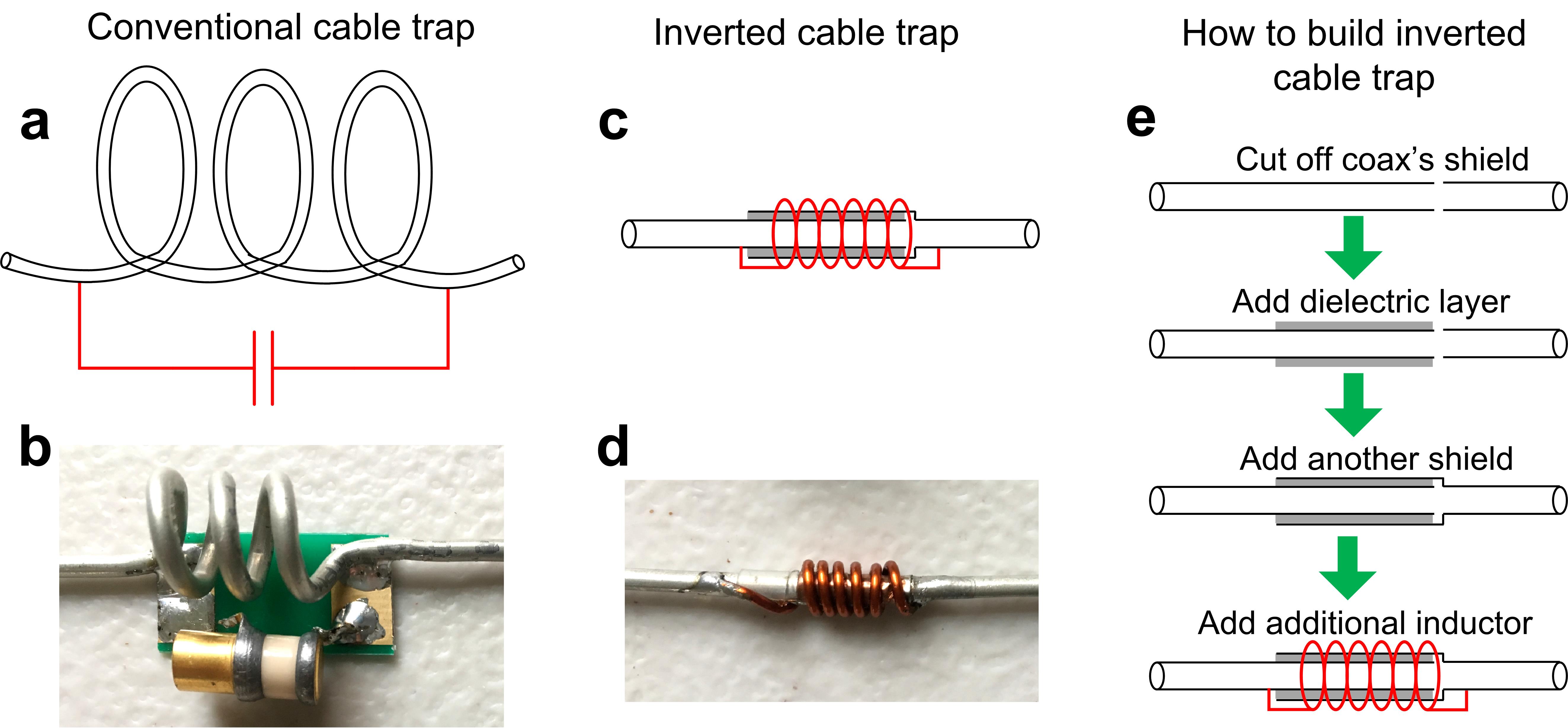
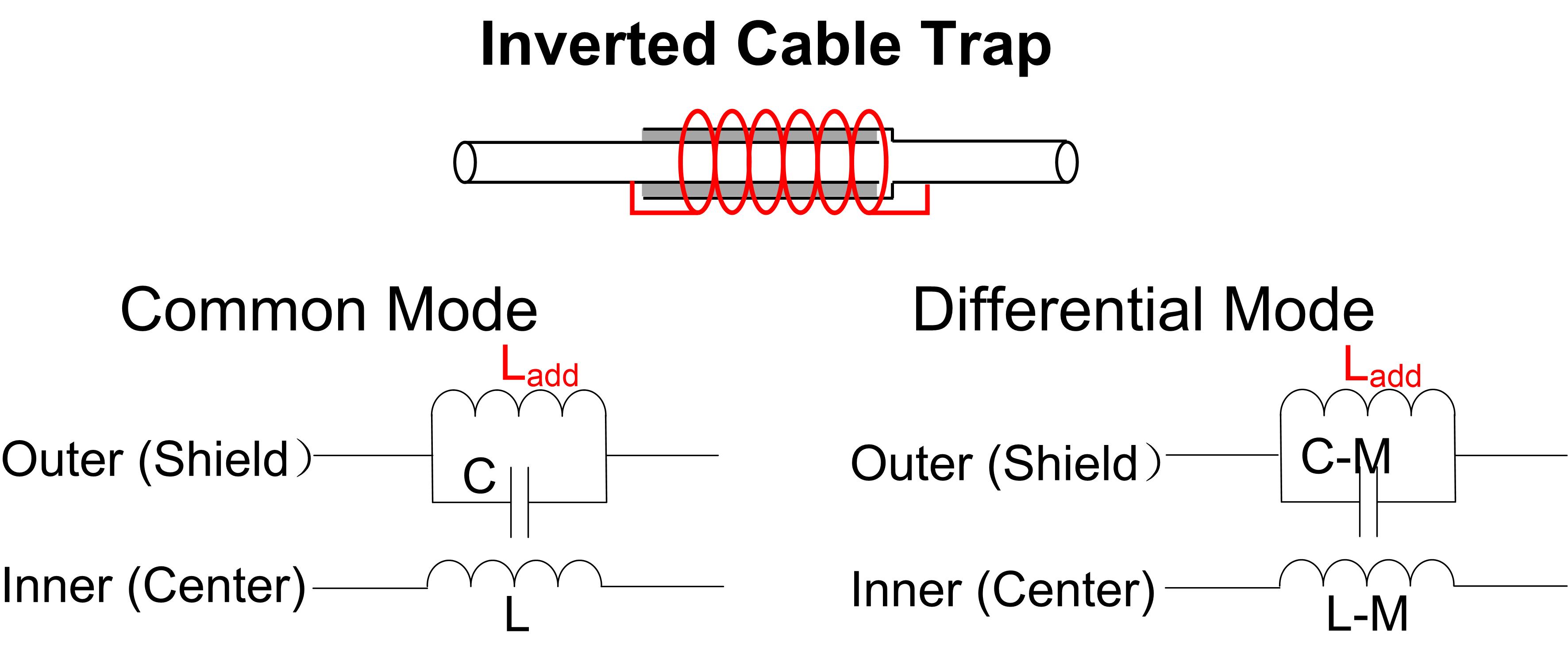
Figure 1a shows the schematic of a conventional trap which uses the coax cable’s outer shielding as an inductor, and with an additional parallel capacitor, to create a resonant circuit at the Larmor frequency. Figure 1c shows the schematic of the proposed inverted trap circuit which uses the coax’s outer shielding to form a capacitor and an additional parallel inductor to resonate. In the inverted cable trap, the additional inductor can be wound tightly around the coax without sacrificing the suppression level, making it a highly miniaturized design. Figures 1b and 1d show photographs of a conventional and novel inverted trap using semi-rigid cables at 298 MHz (proton Larmor frequency at 7T). It is clearly seen that the dimension of the inverted trap is much smaller compared to the conventional design. Figure 2 shows the equivalent circuit of the inverted cable trap. Note that C-M is equal to a capacitance in practice, where C is the equivalent capacitance between the shields of the cables and M is the mutual coupling between the coax’s center conductor and shield 5. Therefore, this C-M may slightly influence the matching performance and induce unwanted loss of the differential-mode signal.
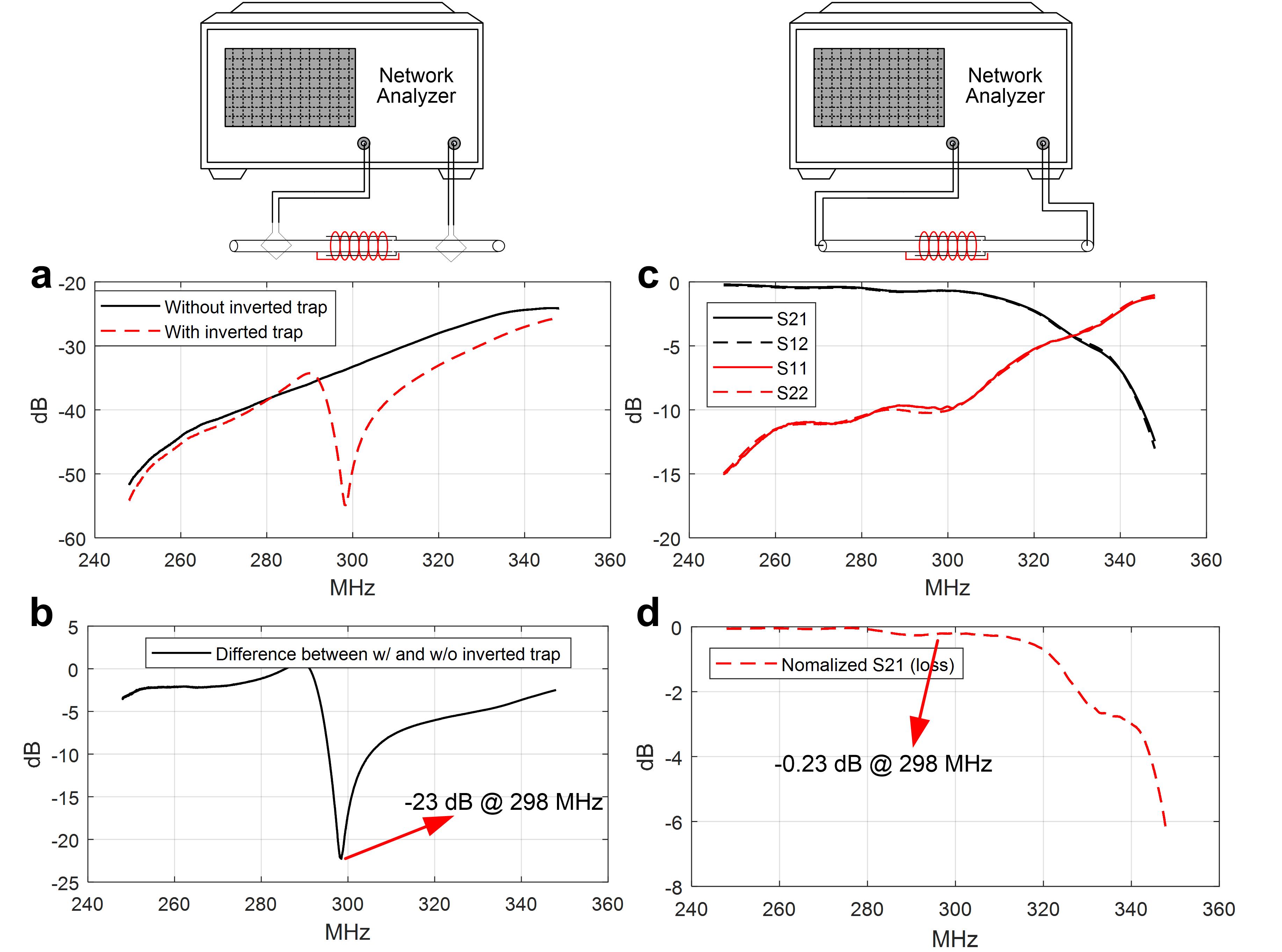
The inverted trap’s performance was evaluated on the bench with a network analyzer. The suppression capability of the common-mode current flow on the outside of coax was tested with two current probes. One current probe transmits current onto the coax’s shielding, whereas the other probe measures the attenuation of this current (evaluated by S21). Unlike the conventional trap, the outer shielding of the coax in the inverted trap is “broken” to form a capacitor, so the matching and loss of the differential-mode signal were measured.
Results
The lumped inductor in the inverted trap was manually adjusted to resonate at 298 MHz with the distributed capacitance. Figure 3a show the S21 plots of two current probes without and with the inverted trap, whereas Figure 3b shows their difference. It can be seen from Figure 3b that current on the coax’s shielding can be reduced to a sufficiently low value by using one inverted trap (-23 dB). Figure 3c shows the S11 and S21 plots of the differential-mode signals. As expected, the matching performance deviated a little from 50 ohm (from <-25 dB to -9.9 dB) and the uncorrected S21 was -0.69 dB (including connectors and 20-cm-long cables). However, it should be noted that the matching can be easily re-matched to 50 ohm by adjusting the coil’s matching circuit and then the loss was only 0.23 dB (Figure 3d).Dicussions and Conclusion
Conventional cable traps need the coaxial cable to form a relatively large solenoid inductor, and thus become bulky in massive array coils. Although floating traps do not need the large solenoid, their outer diameters are quite large (>2 times of coax’s diameter) to ensure sufficient inductive coupling. We found that it is possible to build a highly-miniaturized inverted trap with acceptable common-mode suppression capability (-23 dB). Their physical dimensions are negligible compared to the cable’s dimension (both diameter and length). However, it should also be noted that this inverted cable trap slightly affects the “differential-mode” signal and the matching circuit needs to be re-tuned. Further studies optimizing the dimensions of the inverted trap and analyzing the E-field/heating distribution are warranted.Acknowledgements
No acknowledgement found.References
1. United States Patent: 4682125 - RF coil coupling for MRI with tuned RF rejection circuit using coax shield choke.
2. Seeber, DA, Jevtic J, and Menon A. "Floating shield current suppression trap." Concepts in Magnetic Resonance Part B: Magnetic Resonance Engineering: An Educational Journal 21.1, 26-31 (2004).
3. Holcomb WG and Gore JC. “An improved network for impedance matching and simultaneous unbalanced to balanced transformation.” Magn. Reson. Imag. 3, 295-296 (1985)
4. Chen C-N and Hoult DI, “Biomedical magnetic resonance technology”, Institute of Physics Publishing, Bristol and Philadelphia (1989).
5. Yang X, Zheng T, and Fujita H. "T/R switches, baluns, and detuning elements in MRI RF coils." ISMRM Fourteenth Scientific Meeting Weekend Syllabus. (2006).
Figures