1577
Massively Accelerated Simulations of High-Permittivity Materials in Multi-Channel Receive Arrays1Leiden University Medical Center, Leiden, Netherlands, 2Delft University of Technology, Delft, Netherlands, 3Philips Research Laboratories, Hamburg, Germany
Synopsis
High-permittivity materials are known to offer potential increases in the sensitivity of RF coils, increasing SNR or reducing SAR. Design guidelines are not straightforward, however, in part due to complex coil interactions. We here present a numerical method for the rapid (e.g. ~1 sec) assessment of dielectric materials positioned in a 3T torso receive array, enabling full exploitation of this technology.
Introduction
High-permittivity materials have been shown to be able to improve the receive sensitivity of RF coils, owing to the distributed nature of displacement currents as opposed to the currents in the coil conductors1. Many ongoing efforts are dedicated to developing new materials for this purpose; however rules for their design (in terms of geometry, placement, composition) are difficult to establish due to complex interactions with nearby receive coils.2 Analytical techniques have been demonstrated, but these are limited to very simple sample geometries such as homogeneous spheres or cylinders.3 Numerical approaches allow the incorporation of a realistic body model, but involve large computational meshes which, together with the large number of RF ports involved, lead to prohibitive simulation times when different material configurations need to be evaluated.
In this work we extend a numerical framework previously developed to model dielectric materials in an RF transmit coil, and include model-order-reduction techniques to compress the model and circuit co-simulation to account for nearby receive coil coupling.4 Based on the ultra-fast evaluations of the reduced order model, we show the scalability of this procedure in modeling dielectric materials in a receive array for body-imaging at 3T.
Methods
Coil Model
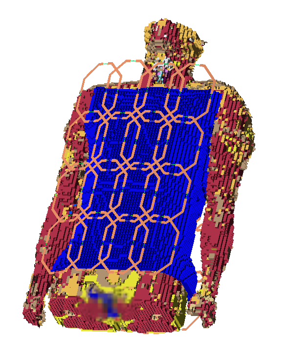
A generic 3T receive array comprising 32 channels was modeled, with geometrically decoupled loops each measuring 8×13 cm in size. Each loop was segmented by four discrete ports resulting in a total of 128 simulated ports, to be combined into 32 channels during circuit co-simulation. The body model “Duke” was used on an isotropic grid with a spatial resolution of 7.5 mm.5 The pad-domain was setup as a 1.5 cm thick layer surrounding the torso, and the coil array was positioned at a fixed distance of 7 cm from the body. The configuration is illustrated in Fig. 1.
Modeling Dielectrics
The dielectric material underneath the coil array was modeled efficiently using model order reduction as outlined in previous work.6,7 In this approach, a perturbation field is solved for a given dielectric, and then added to the background field to obtain the total field. This also provides the perturbation voltages and currents on the ports of the coil model, which account for coil coupling. Furthermore, we compress the model by projecting the underlying system matrix on a reduced-order basis, consisting of 500 current modes extracted from 2500 random pad simulations in a 3T body coil setup. We thereby obtain a reduced system matrix of size 500×500, which can be solved very efficiently using a direct matrix inverse, meaning that this approach scales virtually for free with respect to the number of input ports present in the model.
All customized software was created in MATLAB (R2016a, MathWorks, Natick, MA). Background fields as well as the reduced-order-model were generated using xFDTD (XF7, Remcom inc., PA, USA).
Results/Discussion
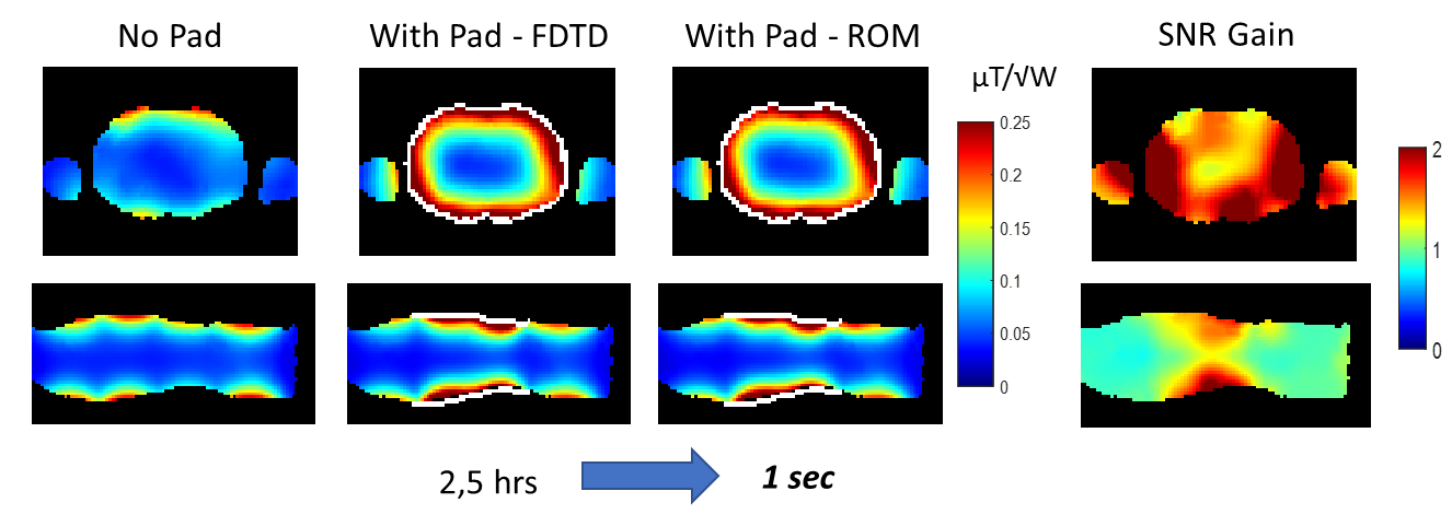
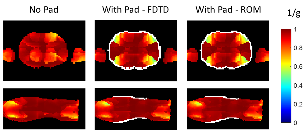
Figure 2 shows an illustrative comparison between SNR simulations obtained through conventional FDTD solvers and the proposed fast method. The dielectric layer was set to have a relative permittivity of 900 and electrical conductivity of 0.2 S/m. Figure 3 shows simulated inverse g-factors corresponding to a high undersampling factor of 3x3x2, to highlight possible effects of the dielectric. Only a very small error is present at the edges of the dielectric, which is due to the truncated order of the reduced order model. The 128 ports of the array model took 2.5 hours to simulate using FDTD, while taking only 1 second using the ROM approach, including circuit co-simulation.
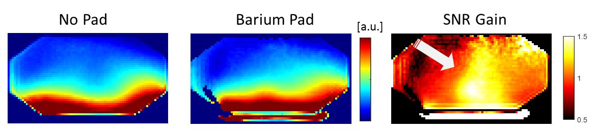
Figure 4 shows example SNR maps measured using the posterior array in a body-sized phantom on a 3T MR system (Ingenia, Philips Healthcare, Best, The Netherlands), acquired using a dynamic noise scan technique and flip angle correction. The SNR was mapped with and without a dielectric pad (εr = 300, σ = 0.2 S/m) in place. Although the permittivity of this specific dielectric is still far from optimal, the array shows improvements in SNR due to the dielectric, reaching local increases of around 50%.
Conclusion
We have developed a simulation technique which enables efficient assessment of dielectric materials in receive array configurations, reaching almost four orders of magnitude acceleration compared to conventional FDTD. This enables more effective design procedures for RF coil designs incorporating dielectric materials, and enables to better exploit this technology.
A stand-alone software package will become available through https://paddesigntool.sourceforge.io to enable other researchers to apply this methodology as well.
Acknowledgements
This project was funded by the Dutch Technology Foundation (STW) project 13375.References
1. Vaidya M V., Collins CM, Sodickson DK, Carluccio G, Lattanzi R. Disentangling Signal propagation and Noise-related Effects in the Presence of High Permittivity Materials via Ideal Current Patterns. In: Proceedings of the 24th Annual Meeting of ISMRM, Singapore. ; 2016. p. 391.
2. Haemer GG, Collins CM, Sodickson DK, Wiggins GC. Discovering and working around effects of unwanted resonant modes in high permittivity materials placed near RF coils. In: Proceedings of the 23rd Annual Meeting of ISMRM, Toronto, Ontario, Canada. ; 2015. p. 0859.
3. Lattanzi R, Vaidya M V, Carluccio G, Sodickson DK, Collins CM. Effects of high-permittivity materials on absolute RF coil performance as a function of B0 and object size. In: Proceedings of the 22nd Annual Meeting of ISMRM, Milan, Italy. ; 2014. p. 4818.
4. Paška J, Froehlich J, Brunner DO, Pruessmann KP, Vahldieck R. Field superposition method for RF coil design. In: Proceedings of the 17th Annual Meeting of ISMRM, Honolulu, Hawaii, USA. ; 2009. p. Proc Int Soc Magn Reson Med 17.
5. Christ A, Kainz W, Hahn EG, et al. The Virtual Family—development of surface-based anatomical models of two adults and two children for dosimetric simulations. Phys Med Biol 2010;55:N23-38. doi: 10.1088/0031-9155/55/2/N01.
6. Van Gemert J, Brink W, Webb A, Remis R. High-Permittivity Pad Design for Dielectric Shimming in Magnetic Resonance Imaging using Projection Based Model Reduction and a Nonlinear Optimization Scheme. IEEE Trans Med Imaging 2018.
7. Brink WM, Paska J, Dai J, et al. Efficient Analysis of Dielectric Materials in Coupled RF Coil Configurations. In: Proceedings of the 25th Annual Meeting of ISMRM, Hawaii. ; 2017. p. 4427.
Figures