1572
A three-element triple-tuned array implemented with switchable matching and tuning1Biomedical Engineering, Texas A&M University, College Station, TX, United States, 2Electrical and Computer Engineering, Texas A&M University, College Station, TX, United States
Synopsis
This work describes a geometrically decoupled three-element array triple-tuned for 1H, 13C, and 31P at 3T implemented with switchable matching and tuning using PIN diodes. These particular nuclei were chosen to demonstrate the frequency range of the method, but the approach is extendable to any nuclei of interest. Although the Q of the coils was degraded by the switching network, the use of PIN diodes enabled straightforward tuning and development.
Introduction
The inherently low signal-to-noise (SNR) of non-1H imaging and spectroscopy studies have led to the development of specialized techniques and hardware to overcome these limitations, including the use of multi-nuclear array coils. Several methods have been used to tune coils to multiple frequencies: the use of traps1, 2, varactor diodes in parallel with fixed capacitors3, and switching mechanisms through the use of MEMS or PIN diodes4-9. MEMS and PIN diodes for switching applications have been compared for Q, power handling, and loss10, 11, and although MEMS technology is improving and shown to be a viable option for different MR applications12, costs of these devices and size of the footprint required could potentially limit their use in array coils requiring multiple switches. Thus, this work describes a geometrically decoupled three-element array triple-tuned for 1H, 13C, and 31P at 3T implemented with switchable matching and tuning using PIN diodes. These three nuclei were chosen to demonstrate the flexible frequency range of the method, but the approach is extendable to any nuclei germane to the scientific study of interest.Methods
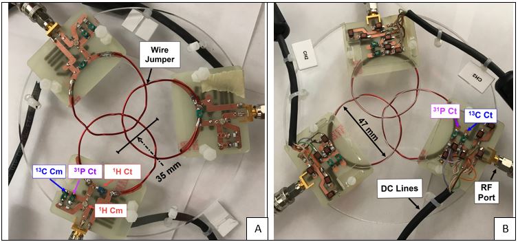
Three 47mm diameter loops were made of 18 AWG nylon-coated copper wire (8049, Belden) with “jumpers” at coil intersections. Each loop was attached to a double-sided copper clad FR4 board containing switching circuitry. The switching circuitry consisted of fixed (1111C, Passive Plus) and variable (SGC3S, Sprague Goodman) matching/tuning capacitors for each frequency, PIN diodes (MA4P7470F, M/A-COM), and RF chokes (1812LS, Coil Craft), detailed in Fig. 1A. A category 5 cable bundle with six DC lines was attached to each coil to allow switching between the three frequencies of interest at 3T: 32.13 MHz (13C), 51.72 MHz (31P), and 127.74 MHz (1H). Each DC cable bundle was connected to two DC lines, corresponding to the 31P and 13C frequencies, coming from the “bias distribution board”, as shown in Fig. 1B and Fig. 2. Each DC line had an RG174 co-axial cable (7805, Belden) with a BNC connector (031-315-RFX, Amphenol) connected to the power supply, an RF choke, and a current-limiting resistor (CRCW0402 Series, Vishay). Each DC line on the bias distribution board was independently controlled to switch between the three frequencies for each element. When all DC lines were connected to the power supply, all PIN diodes were biased to match and tune each coil to the 13C frequency; 31P tuning and matching was achieved by disconnecting the 13C DC lines; DC current was removed for matching and tuning to the 1H frequency.
Each element was matched and tuned separately, and all three were mounted on an acrylic former and positions adjusted for decoupling. Single-tuned coils for each frequency were created for comparison. Benchtop measurements of S21 coupling, S11, and Q measurements were obtained using an Agilent Technologies Network Analyzer (E5071C).
Results
The constructed three-element array and switching networks are shown in Fig. 3A and Fig. 3B. Matching and tuning for each element at each frequency was better than -20.1 dB, as shown in Fig 4. A de-identified video of the coils switching frequencies is available at https://youtu.be/rvtAmE4l-L0. The switching mechanism enabled straightforward tuning at the different frequencies and limited additional coil resonances. Q measurements, shown in Table 1, reveal a significant loss in Q for the triple tuned coils. The drop in Q pertaining to all three frequencies can be attributed to the additional circuitry needed for switching. Coupling measurements reflect that the positioning of the array coils was optimized for the 1H frequency. Although the circuit path for 31P and 13C was similar to that of 1H, the additional circuit path needed for the capacitors could be the cause for the increased coupling at these two frequencies.Conclusion
A three-element triple-tuned switchable phased array coil design was demonstrated with benchtop measurements. Inter-element coupling was sufficient between the different channels. The use of PIN diodes enabled straightforward tuning and development, but this was achieved at the expense of the Q of the coils. In its current form, the increase in sensitivity achieved with the array is essentially canceled by the loss in Q. Therefore, future directions include exploring ways to improve the Q, such as using an inductor in series with the PIN diode to tune to the 1H frequency as suggested by Choi6. Optimizations for the number of breaks and size of the coil can also be performed to influence the Q at different frequencies8. Following optimizations, imaging and spectroscopy studies will be performed to validate benchtop performance and the use of switchable, triple-tuned phased array coils.Acknowledgements
No acknowledgement found.References
[1] M. Meyerspeer, E. S. Roig, R. Gruetter, and A. W. Magill, "An improved trap design for decoupling multinuclear RF coils," Magnetic Resonance in Medicine, vol. 72, no. 2, pp. 584-590, 2014.
[2] M. D. Schnall, V. Harihara Subramanian, and J. S. Leigh, "The application of overcoupled tank circuits to NMR probe design," Journal of Magnetic Resonance (1969), vol. 67, no. 1, pp. 129-134, 1986.
[3] L. T. Muftuler, G. Gulsen, K. D. Sezen, and O. Nalcioglu, "Automatic tuned MRI RF coil for multinuclear imaging of small animals at 3T," J Magn Reson, vol. 155, no. 1, pp. 39-44, Mar 2002.
[4] S. B. Bulumulla, E. Fiveland, K. Park, and J. Iannotti, "MEMS Reconfigurable Coils," Proc. Intl. Soc. Mag. Reson. Med., no. 23, pp. 1797-1797, 2015.
[5] S. B. Bulumulla, K. J. Park, E. Fiveland, J. Iannotti, and F. Robb, "MEMS switch integrated radio frequency coils and arrays for magnetic resonance imaging," Rev Sci Instrum, vol. 88, no. 2, p. 025003, Feb 2017.
[6] C. H. Choi, S. M. Hong, Y. Ha, and N. J. Shah, "Design and construction of a novel 1H/19F double-tuned coil system using PIN-diode switches at 9.4T," J Magn Reson, vol. 279, pp. 11-15, Jun 2017.
[7] C. H. Choi, J. M. Hutchison, and D. J. Lurie, "Design and construction of an actively frequency-switchable RF coil for field-dependent Magnetisation Transfer Contrast MRI with fast field-cycling," J Magn Reson, vol. 207, no. 1, pp. 134-9, Nov 2010.
[8] S. Ha, M. J. Hamamura, O. Nalcioglu, and L. T. Muftuler, "A PIN diode controlled dual-tuned MRI RF coil and phased array for multi nuclear imaging," Phys Med Biol, vol. 55, no. 9, pp. 2589-600, May 7 2010.
[9] A. Maunder, M. Rao, F. Robb, and J. Wild, "RF coil design for multi-nuclear lung MRI of 19F fluorinated gases and 1H using MEMS," Proc. Intl. Soc. Mag. Reson. Med., no. 24, pp. 3504-3504, 2016.
[10] M. Fuentes, E. Weber, S. Wilson, B. Li, and S. Crozier, "Micro-Electromechanical Systems (MEMS) based RF-switches in MRI – a performance study," Proc. Intl. Soc. Mag. Reson. Med., no. 18, pp. 422-422, 2010.
[11] A. Maunder, M. Rao, F. Robb, and J. M. Wild, "Comparison of MEMS switches and PIN diodes for switched dual tuned RF coils," Magnetic Resonance in Medicine, vol. 80, no. 4, pp. 1746-1753, 2018.
[12] D. Spence and A. Macro, "Custom MEMS switch for MR surface coil decoupling," Proc. Intl. Soc. Mag. Reson. Med., no. 23, pp. 704-704, 2015.
Figures