1568
Effect of high dielectric constant material configurations on the transmission field of an 8-channel dipole array at 10.5 T (447 MHz)1Pennsylvania State University, College of Medicine, Hershey, PA, United States, 2Department of Engineering Science and Mechanics, Pennsylvania State University, State college, PA, United States, 3Department of Radiology, The Bernard and Irene Schwartz Center for Biomedical Imaging, New York University, New York, NY, United States, 4Center for Magnetic Resonance Research, University of Minnesota, Minneapolis, MN, United States
Synopsis
We used numerical simulations to investigate the effect of high dielectric constant materials (HDCM) on the performance of a transmit array with 8 dipole antennas for 10.5 T head MRI. Several parameters, including B1+ transmit efficiency, coupling between each array elements, and Specific Absorption Rate (SAR), were evaluated in the presence of HDCM with various relative permittivity values. We show that employing HDCM can decrease the coupling between each adjacent element by 16%, increase B1+ efficiency by more than 30% and lower total SAR by 40%.
Introduction
With the introduction of whole body 10.5 T scanner to once again push the resolution and information content of human brain images to a new levels 1, the associated higher frequency (447 MHz) of the RF field requires us to carefully re-evaluate and characterize the RF field behavior and coil design options for optimal transmission efficiency and safety. In parallel, incorporation of high dielectric constant materials (HDCM) into RF coils has been shown to be effective in reduction of transmission power while enhancing image SNR 2,3, which would alleviate some of the challenges in RF coil development for ultrahigh field MRI. Thus, it is synergistic to incorporate HDCM into RF coil designs for the 10.5T system. In this work, we numerically investigate the effect of different permittivity of HDCM on a dipole antenna transceive array in terms of changes in B1+ efficiency, coupling between coil elements and overall SAR and demonstrate the improvements in increasing B1+ efficiency and reduced coupling between coil elements and overall SAR.Methods
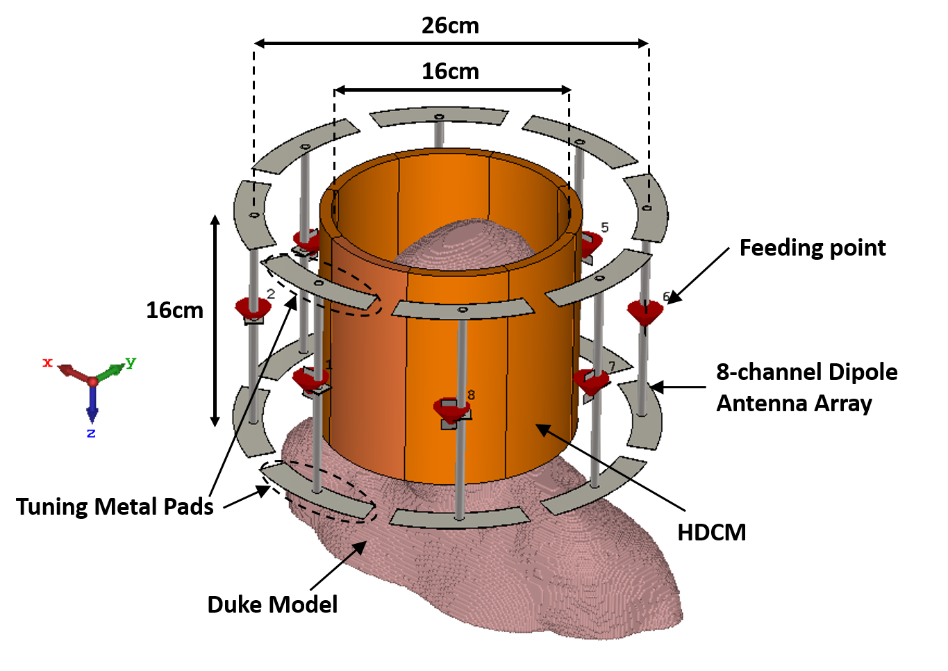
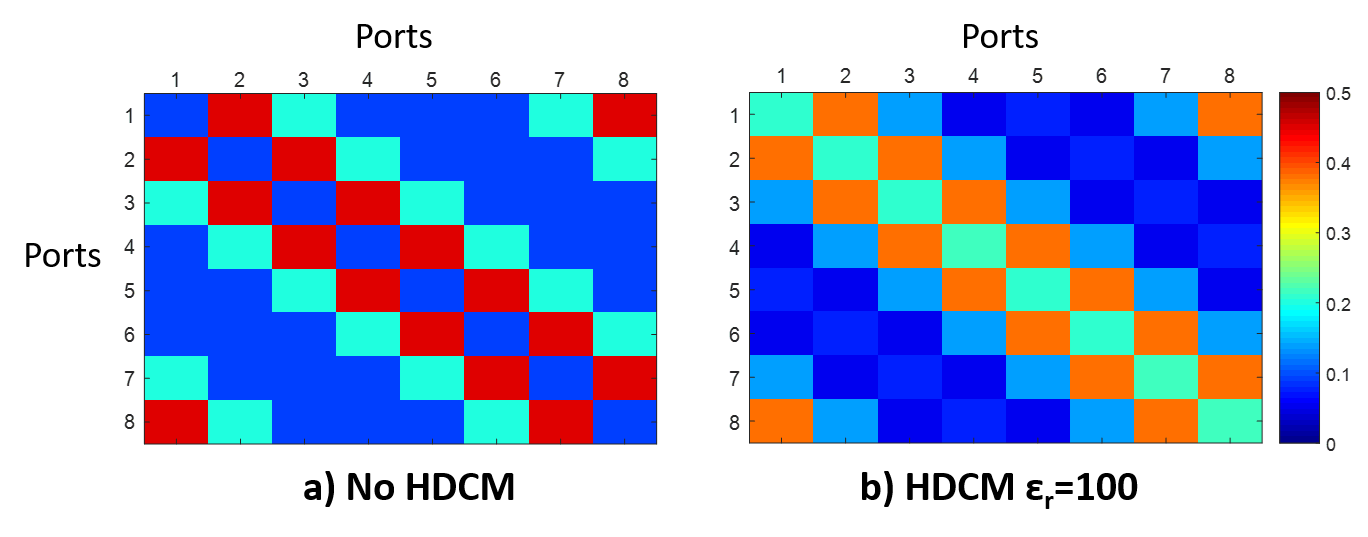
Simulation: All the simulations have been performed in CST Microwave Studio 4. Dipole antenna array: As previously reported 5 and shown in Fig.1, the proposed 10.5 T MRI RF coil is comprised of eight 16cm-long dipole antenna elements arranged azimuthally over a 26cm diameter cylinder and simply driven to create field with circular polarization. For tuning the resonant frequency to 447MHz, we varied the length of metallic pads placed at both ends of each element. HDCM around human model: The Duke human head model 6 has been used as the sample, and is surrounded by cylindrical shells with different relative permittivity of 8mm thick 16cm-diameter cylindrical HDCM (εr=50, εr=100) shell. The transmit efficiency and SAR values has been calculated. The transmit efficiency is calculated by dividing B1+ over the square root of the dissipated power in the human head. To remove the effect of flip angle on SAR calculation, we have normalized all of our calculations to the average value of B1+ field. All the calculations are compared with the case of no HDCM around the head. Coupling: Each of 8 dipole antenna are excited individually and the S-parameters are extracted at 447MHz in an 8x8 matrix. The coupling has been studied by considering the Sij (i≠j), where “i” and “j” are the index number of each antenna element in two scenarios: 1-without and 2-with HDCM over a water phantom (εr=81, σ=0.69 S/m) as the sample. The cylindrical water phantom is chosen to have a symmetrical response.Results and Discussion
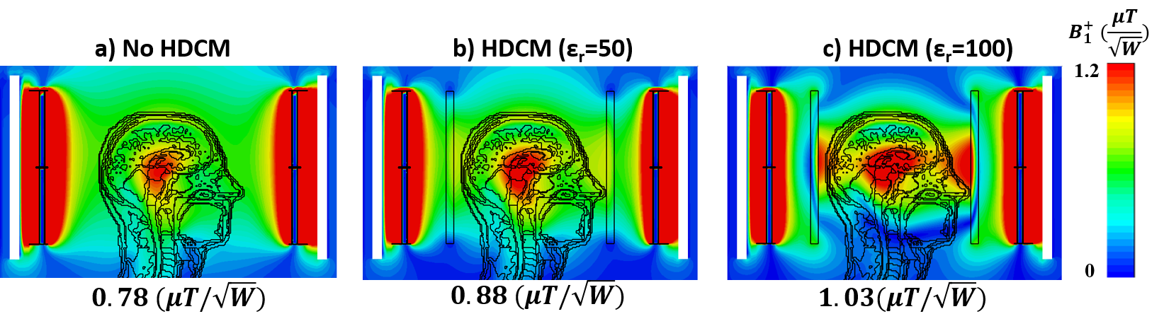
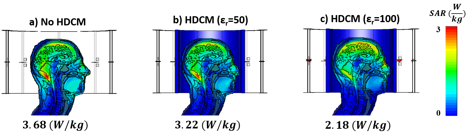
Transmit Efficiency: Fig.2 shows the sagittal view of transmit efficiency of the dipole array from human head model for 3 cases of no HDCM, HDCM with εr=50 and εr=100 around the model. The averaged B1+ value within the human head is also written under each snapshot. As shown in the figure, the transmit efficiency is boosted by more than 30% using HDCM with εr=100. One contributing factor for transmit efficiency improvement is the reduction of radiation field from dipole antenna. Normalized SAR values: Fig. 3 shows the normalized SAR maps of a sagittal cross-section for the three cases. Maximum SAR is written under each map. It is shown that the SAR value has also been decreased around 40% using HDCM with εr=100. This results can be described by the shielding of non-conservative electric field by the HDCM. Since the electric field is maximum at both ends of the dipole antenna, the HDCM with similar length of the dipole can shield the electric field effectively from penetrating into the human head and decrease the resulting SAR. This effect is critically important for the heightened safety concerns for performing MRI studies at such high field strength. Coupling: The simulation of S-parameters in 2 cases without and with HDCM showed that using HDCM the coupling between each neighboring element was decreased around 16% (Fig. 4). The reason for the observed phenomenon was that the dielectric material around the phantom increases the coupling between the sample and reduced the coupling between the neighboring elements.Conclusion
Employing HDCMs (εr=50 and εr=100) with dipole antenna array could address the challenges for human studies at ultrahigh and extremely high magnetic fields where SAR and radiation loss are expected to increase significantly. By employing HDCMs the B1+ field efficiency is enhanced and the SAR value has decreased. HDCMs also reduced coupling between neighboring elements directing more RF energy to the sample under study. Future work includes studying optimized permittivity values as well as HDC configuration (discrete configuration) to further enhance all of the above-mentioned parameters.Acknowledgements
This work was supported by NIH grants including U01 EB025144, and R01 EB024536.References
1. Ertürk, M.A., X. Wu, Y. Eryaman, et al., Toward imaging the body at 10.5 tesla. Magnetic Resonance in Medicine, 2016. 77(1): p. 434-443.
2. Yang, Q.X., S. Rupprecht, W. Luo, et al., Radiofrequency field enhancement with high dielectric constant (HDC) pads in a receive array coil at 3.0T. Journal of magnetic resonance imaging : JMRI, 2013. 38(2): p. 435-440.
3. Rupprecht, S., C.T. Sica, W. Chen, M.T. Lanagan, and Q.X. Yang, Improvements of transmit efficiency and receive sensitivity with ultrahigh dielectric constant (uHDC) ceramics at 1.5 T and 3 T. Magnetic Resonance in Medicine, 2017. 79(5): p. 2842-2851.
4. https://www.cst.com/.
5. Lagore, R.L., L. DelaBarre, J. Tian, G. Adriany, Y. Eryaman, J.T. Vaughan, End-Loaded Dipole Array for 10.5T Head Imaging. Proc. Intl. Soc. Mag. Reson. Med. 24 (2016) p. 2138.
6. Andreas, C., K. Wolfgang, G.H. Eckhart, et al., The Virtual Family—development of surface-based anatomical models of two adults and two children for dosimetric simulations. Physics in Medicine & Biology, 2010. 55(2): p. N23.
Figures