1567
MEMS-based Ratio Adjustable Power Splitters for in-bore Switching of Transmit Array Compression Networks1Department of Biomedical Engineering, Vanderbilt University, Nashville, TN, United States, 2Vanderbilt University Institute of Imaging Science, Nashville, TN, United States, 3Department of Electrical Engineering and Computer Science, Vanderbilt University, Nashville, TN, United States, 4Department of Radiology, Vanderbilt University, Nashville, TN, United States, 5Department of Electrical Engineering, Vanderbilt University, Nashville, TN, United States
Synopsis
A large number of coils in parallel transmission enables higher excitation accuracy with lower SAR, but the high cost and siting challenges associated with
Introduction
A large number of coils in parallel transmission enables higher excitation accuracy with lower SAR [1], but the high cost and siting challenges associated with transmit amplifiers and their cabling has limited the number of channels to 8 on most 7T scanners. To overcome this limitation, we are developing hardware networks that sit between the amplifiers and coils and will enable a large number of coils to be optimally driven by a small number of channels [2,3]. These networks comprise ratio adjustable power splitter (RAPS) circuits that use hybrid couplers terminated by reflection capacitors to apply relative phase shifts between signal branches that can be tuned to set coil output power ratios [4,5]. To enable remote control for dynamic coil optimization, we previously described a RAPS circuit that used PIN diodes to switch between banks of reflection capacitors. Due to the isolation impedance of PIN diodes (~2-3pF) which complicates circuit design and their higher current consumption, in this work, we describe and evaluate an MR-compatible MEMS-RAPS circuit that uses RF MEMS switches [6] instead of PIN diodes for more ideal switching performance.Methods
Circuit Design and Construction
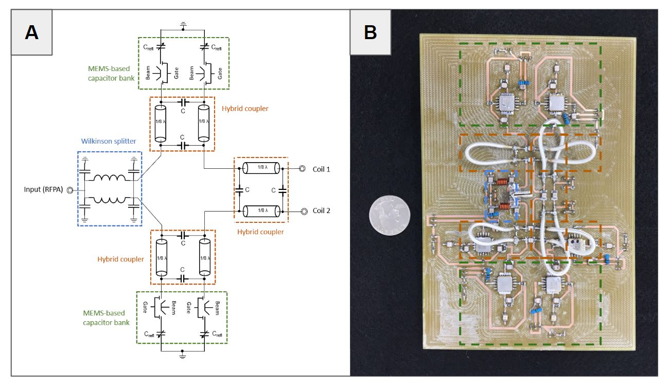
Figure 1 shows a schematic and a constructed MEMS-RAPS circuit. The transmit amplifier inputs into the circuit’s Wilkinson divider. The split power is then phase-shifted and combined by three hybrid couplers. The values of the terminating capacitors on two of the hybrid couplers determines the power ratio at the output to each coil [3]. One branch had 10pF reflection capacitors and the other branch had an option of 2pF or 5.1pF; all were made switchable. With these capacitors, the nominal achievable output voltage ratios for this circuit were 1 (MEMS off-state), 2 (10pF and 5.1pF), and 4.5 (10pF and 2pF).
Bench Test and Imaging Validation
The MEMS-RAPS circuit was constructed, tuned, and matched at 298 MHz (7T). Bench tests were performed to validate it, measuring the voltage and power ratios. The circuit was placed in a 7T Philips Achieva Scanner (Best, Netherlands) between the amplifier and the 0-degree port of a birdcage coil, with the other port terminated. Using the DREAM method [7], B1+ maps were measured and the flip angles in a region of interest in the center of a mineral oil phantom were calculated to measure the actual ratios and calculate power loss.
Results
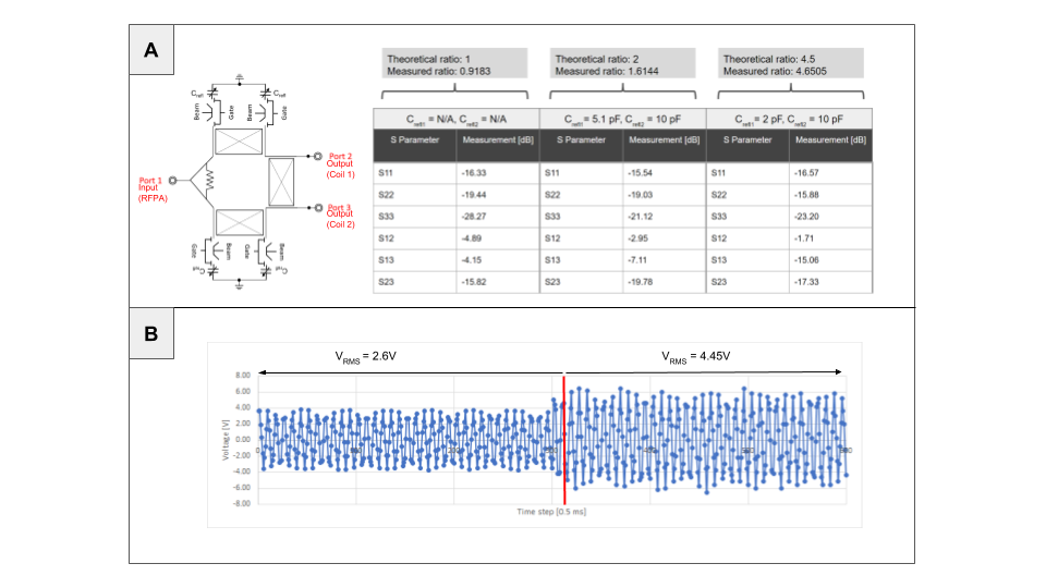
Figure 2a shows the bench test results including port matching, isolation, and loss measurements. Each port was matched to better than -15.5dB and isolation between the output ports was better than -15.8dB. The presence of two versus four MEMS and their associated traces and components on each side of the circuit led to a 0.74dB difference in matching between the output ports. Overall, the power loss on the bench ranged from 23- 35% including adapter losses. The switching speed was characterized on the bench to be approximately 500 us (Figure 2b).
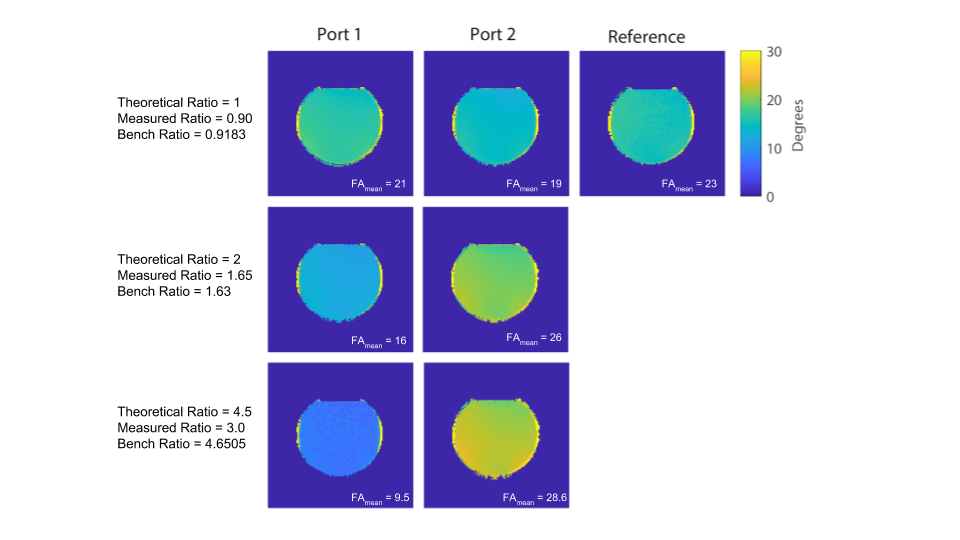
The B1+ maps (Figure 3) further verify that the MEMS-RAPS circuit can be switched inside the scanner. The theoretical ratio, the measured ratio, and the bench ratio are in good agreement for the MEMS-off state. For the nominal ratio of 2, the measured ratio and the bench results are in good agreement. For the 4.5 ratio, the measured ratio was further from the theoretical and bench results, possibly due to noise bias in the map measured using the low-output port. The B1+ maps further confirmed the loss from the bench tests, which ranged from 20-38%. Heating was measured using an infrared thermometer. There was no detectable temperature rise in the MEMS switches or elsewhere in the circuit after the DREAM scan, and it continued to function without defects.
Discussion
We introduced a MEMS-RAPS circuit that uses classic RF building blocks (Wilkinson splitters and hybrid couplers) combined with MEMS switches to enable remotely tunable transmit array compression networks. If both phase shifter branches were symmetric, the loss should be reduced to about 20%. The switching time was 500us which is sufficient for most applications but could likely be reduced using a custom driver and controller.
An important consideration is power handling and the capability to withstand at least 1kW peak per transmit channel [8]. No heating issues were observed with the large flip angle pulses used in the DREAM sequence with a relatively high duty cycle, which suggests the circuit should be able to withstand high power with moderate duty cycle.
Conclusion
We have validated the use of RF MEMS as the switching mechanism for a RAPS network. The overall goal of this project is to create a low loss network allowing the use of more transmit channels driven by a smaller number of RF power amplifiers.Acknowledgements
Supported by NIH R01 EB 016695 and U01 025162.References
1. Zhu, Y. (2004). Parallel excitation with an array of transmit coils. Magnetic Resonance in Medicine: An Official Journal of the International Society for Magnetic Resonance in Medicine, 51(4), 775-784.
2. Cao, Z., Yan, X., & Grissom, W. A. (2016). Array‐compressed parallel transmit pulse design. Magnetic resonance in medicine, 76(4), 1158-1169.
3. Yan, X., Cao, Z. and Grissom, W. A. (2017), Ratio-adjustable power splitters for array-compressed parallel transmission. Magn. Reson. Med..doi:10.1002/mrm.26847.
4. Yan X, Cao Z, Grissom WA. Experimental implementation of array-compressed parallel transmission at 7 Tesla. Magn Reson Med 2016;75:2545–2552.
5. Sappo CR, Yan X, Grissom WA. Tunable phase shifters and ratio-adjustable power splitters for array-compressed parallel transmission and MR Fingerprinting. In: Proceeding of the 26th Annual Meeting of ISMRM, Paris, France; 2018 (Abstract 7199).
6. Maunder, A., Rao, M., Robb, F., & Wild, J. M. Comparison of MEMS switches and PIN diodes for switched dual tuned RF coils. Magn Reson Med, 2018.
7. Nehrke K, Bornert P. DREAM - A novel approach for robust, ultrafast, € multislice B1 mapping. Magn Reson Med 2012;68:1517–1526
8. Yazdanbakhsh, P., & Solbach, K. Microstrip Butler matrix design and realization for 7 T MRI. Magn Reson Med 2011, 66(1), 270-280.
Figures