1565
The miniaturisation and simplification of a crossbar switch matrix system using stacked switch blocks1Institute of Neuroscience and Medicine - 4, Forschungszentrum Juelich, Juelich, Germany, 2Institute of Neuroscience and Medicine 11, INM-11, JARA, Forschungszentrum Jülich, Juelich, Germany, 3JARA - BRAIN - Translational Medicine, Aachen, Germany, 4Department of Neurology, RWTH Aachen University, Aachen, Germany
Synopsis
The crossbar-type matrix creates open-stubs of varying length, depending on the switch configuration, which potentially degrades the MR image quality. However, this issue can be overcome efficiently with the use of a compensation circuit. But as the number of receive coils increases, a larger number of RF switches is required. In this study, we propose a miniaturised crossbar switch matrix which employs two independent, stacked boards.
Introduction
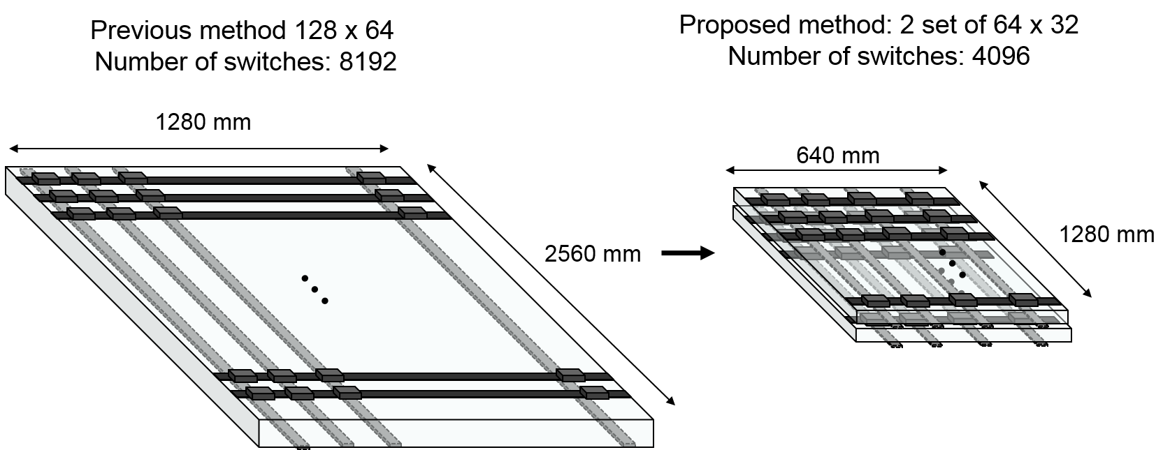
In recent years, the use of multi-channel phased array coils has become common practice in MRI. This is largely due to the outstanding improvements they offer in terms of signal-to-noise ratio (SNR) and in the feasibility of accelerating acquisitions1. Receive coils are frequently connected via crossbar-type switch matrixes. These use RF switches to route the receive signals to appropriate receive paths2, which reduces the number of hardware circuits required. This crossbar-type matrix, however, creates open-stubs of varying length, depending on the switch configuration, which potentially degrades the MR image quality. However, this issue can be overcome efficiently with the use of a compensation circuit3. As the number of receive coils increases, a larger number of RF switches is required. Thus, the size of the switch matrix board gets larger, causing elevated losses on the long transmission lines of the PCB. For example, a 128 (input) x 64 (output) matrix requires 8192 switches, and the size of the board can be as big as 2560 mm x 1280 mm (assuming a spacing of 2 cm between neighbouring transmission lines - which is realistic to avoid cross talk between long parallel lines). In this study, we propose a miniaturised crossbar switch matrix which employs two independent, stacked boards.Methods
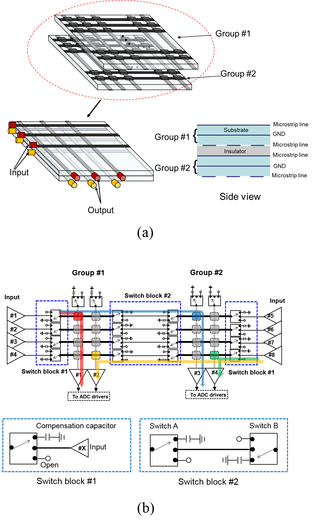
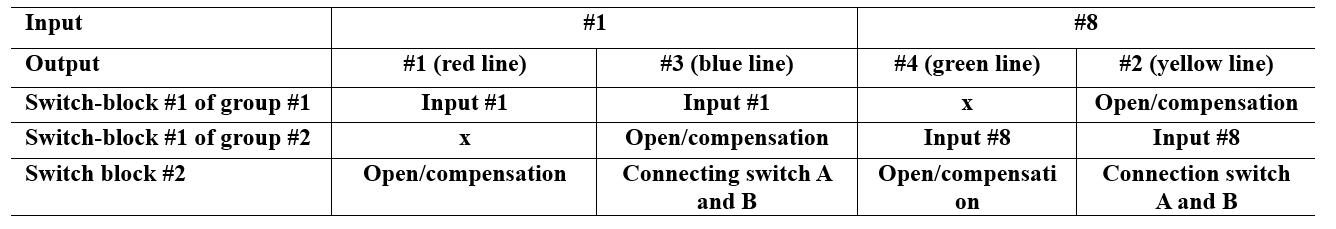
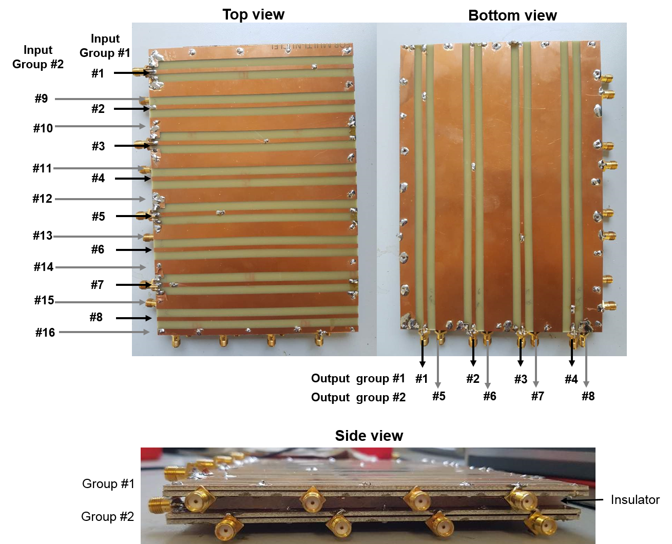
Fig. 1(a) shows the proposed crossbar switch matrix configuration which was modified from the conventional, dual layer switch matrix. In the novel design, two independent matrix boards were stacked together via an insulator between the boards and two switch blocks were used (Fig. 1(b)). The switch blocks #1 and #2 allow two independent boards to be connected, in which the switch block 1 is located on the input port, enabling one to select between the input, open, and compensation capacitor. Switch block #2 is located between the two boards, enabling the selection of open, compensation capacitor, and connecting switches A and B. Fig. 2 shows a 16 x 8 (f = 400MHz) switch matrix created by stacking two 8 x 4 switch matrices built from double-layer FR4 PCBs and implemented for validation purposes. In order to evaluate the quality of the proposed design, the insertion losses of the implemented switch matrix in all channels were measured using a network analyser (ZVR, Rhode & Schwarz, Germany).Results
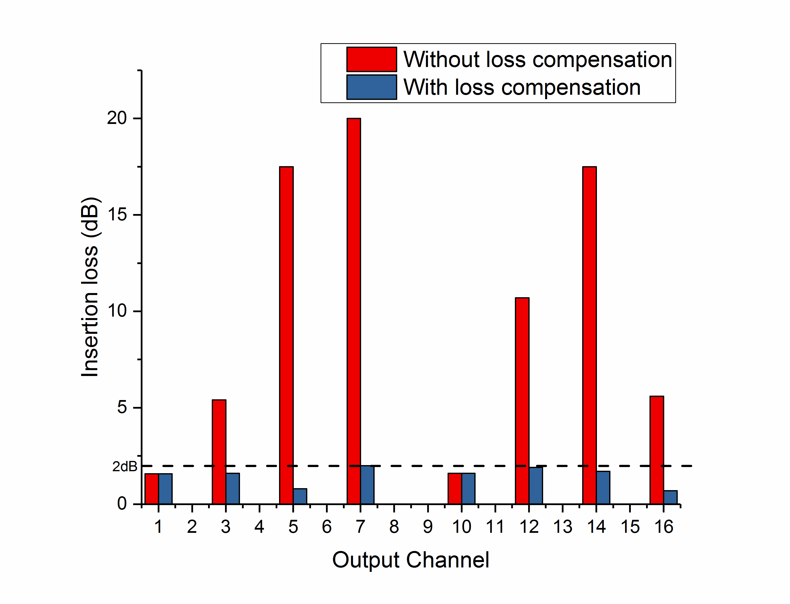
Fig. 1(b) shows an example of the 8 x 4 switch matrix operation. Table 1 gives the configuration of switch block #1 and #2 for some exemplary input-output configurations. Note that with the proposed switch topology, it is possible to connect any input port with any output port. Fig. 3 shows the measured insertion loss of the prototype switch matrix. The insertion losses could be maintained below 2 dB when using the proposed compensation method. Fig. 4 illustrates the space savings for the proposed matrix implementation in comparison with the conventional design. This result shows that, even if the number of channels increases, the crossbar-type switch matrix can be applied and it maintains its flexibility.Discussion
A previous study3 has demonstrated that crossbar switch matrixes can be implemented in ultra-high field MRI when proper compensation is applied. However, as the number of channels increases, the number of switches and board size increase, making the conventional implementation costly and bulky. This miniaturisation and simplification method shows the number of switches can be reduced by a factor of 2 and the size of the board can be decreased to ¼.Acknowledgements
We would like to thank Claire Rick for proofreading, and Annette Weber for her assistance in preparing the PCBs used in this study.References
[1] P. B. Roemer, W. A. Edelstein, C. E. Hayes, S. P. Souza, and O. Mueller, "The NMR phased array," Magnetic resonance in medicine, vol. 16, no. 2, pp. 192-225, 1990.
[2] Kröckel H. "Switching matrix with two control inputs at each switching element." U.S. Patent 11 283 274, Mar. 23, 2010.
[3] Y. Ko, C.-H. Choi, N. J. Shah, and J. Felder, "Signal Loss Compensation of RF Crossbar Switch Matrix System in Ultra-High Field MRI", IEEE transactions on biomedical circuits and systems, 2018.
Figures