1564
Effects of Parallel Imaging Acceleration on SNR Improvement with a High-Permittivity Helmet Shaped Former at Different Field Strengths1Radiology, Center for Advanced Imaging Innovation and Research (CAI2R), New York, NY, United States, 2Radiology, Bernard and Irene Schwartz Center for Biomedical Imaging, New York, NY, United States, 3University of Minnesota, Minneapolis, MN, United States
Synopsis
Use of high-permittivity materials has recently shown very promising results in terms of reduction of B1 inhomogeneities and increase of SNR. In particular, significant SNR increases have been predicted for a high-permittivity helmet former within a close fitting head array. With this solution, for a 7T MRI system, an average SNR increase approaching 50% was obtained in the brain with SNR peak improvements of more than 200%. Until now, however, the effects of the high-permittivity helmet on g-factor and parallel imaging have not been examined. In this work, for three different acceleration rates we evaluate the impact of gfactor when a high-permittivity helmet shaped former is used in two different head arrays at two different field strengths.
Introduction
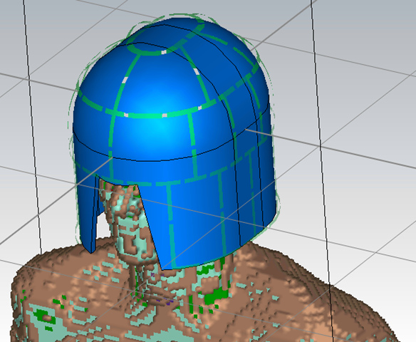
There is a growing interest in the use of high-permittivity materials (HPM) to enhance SNR in MRI. The high-permittivity material creates strong displacement currents which act as additional RF field sources and affect the field distribution in the patient. In fact, it was shown that proper design of HPM geometries can provide higher transmit efficiency, lower peak local SAR, higher B1 field homogeneity and higher SNR. Specifically, an HPM helmet-shaped former was used with a close-fitting array to increase SNR in the head (Fig. 1). In simulations, for a 7T MRI system, it was possible to achieve an average SNR increase of about 48% with an 8 channel receive array coil1, and 51% with a 28 channel receive array2, with local peak SNR gain of 220% in the periphery. Permittivity and geometry (size and thickness) of the material need to be properly designed to achieve optimum performance considering the operating frequency. In this work, through simulations we evaluate the SNR gain when a high-permittivity helmet former is used with a receive array for at two different field strengths (7T and 10.5T) with two different head arrays, and two different acceleration rates (2, and 4) in different directions.Methods
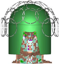
Electromagnetic simulations were performed with the commercial software Microwave Studio (CST 2017, Darmstadt, Germany). A close fitting receive array was positioned around the helmet former,. The array is composed of 28 channels for the 7T system (Figure 1), and 32 channels for the 10.5T system (Figure 2). We first estimated the optimum permittivity of the helmet for the respective operating frequency: for an 8mm thick helmet, we selected a permittivity of 115, and 50 for the proton frequencies of 7T and 10.5T systems. Then, each loop of the array was separately tuned and matched at the corresponding frequency. For each frequency we repeated the computations by assigning the helmet the permittivity of air in order to estimate the impact of the helmet. Assuming that the transmitted field is perfectly homogeneous, the SNR without any acceleration method SNR0 was computed with the equation3: $$$SNR_0 = \sqrt{\Psi R^{-1} \Psi^*} (1)$$$ where denotes the sensitivity matrix, and R the noise covariance matrix.When the receive array is used with acceleration methods, the SNR degrades with the gfactor g according to the relationship $$$SNR = SNR_0 /gR (2)$$$ For the two different field strengths and for two different acceleration rates (2 and 4), the effective SNR was computed with and without the helmet , and the SNR improvement as the ratio $$$SNR_{Ratio}= SNR_{Helmet}/SNR_{Air}$$$Results and Discussion
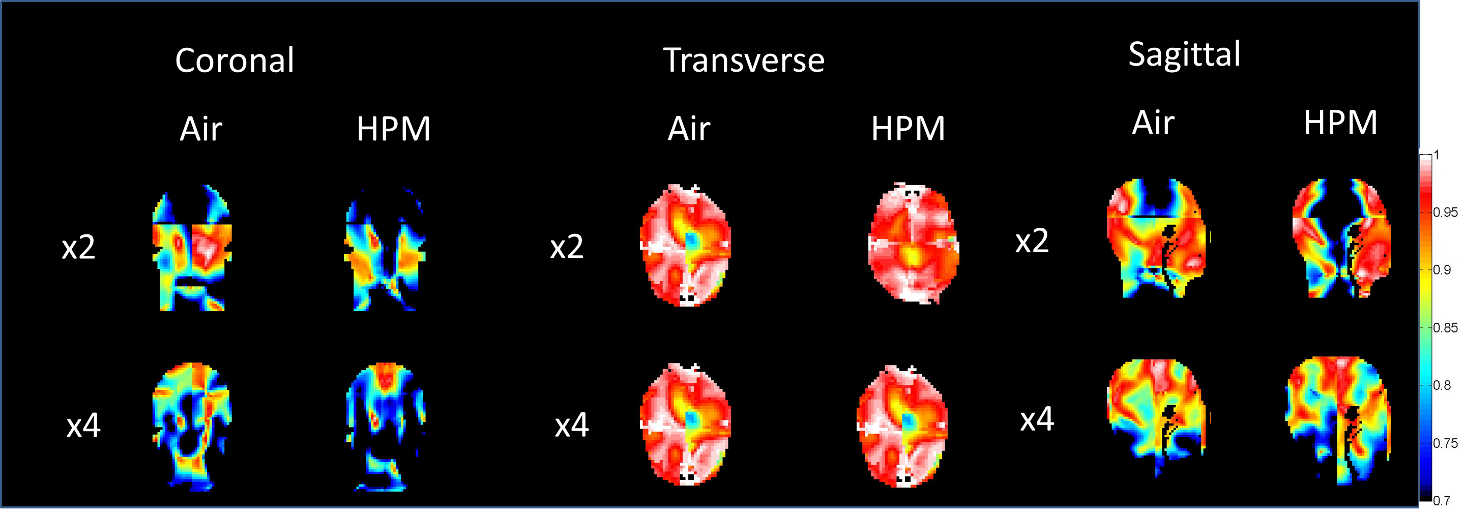
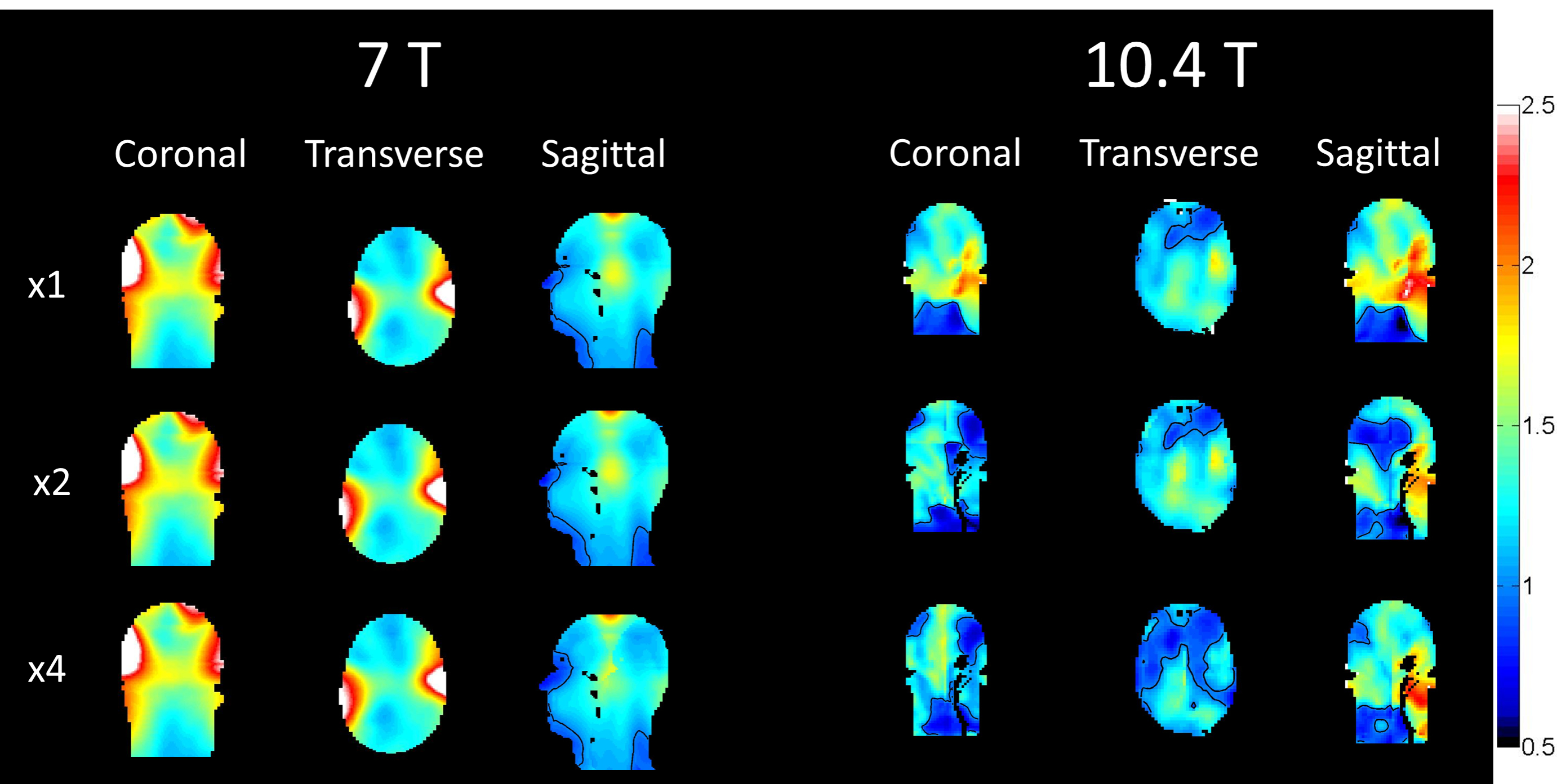
For three different orthogonal acceleration directions, we have plotted the inverse gfactor (1/g) distribution for the 10.5T simulations in Figure 3 (higher values indicate adverse impact on the original SNR), and the SNRRatio in Figure 4. Inverse gfactors distribution for the 7T systems were previously presented4. Figure 3 reveals an increase in gfactor in some cases when the HPM helmet is used. However, this increase does not come close to eliminating the tremendous overall SNR improvement due to the use of the helmet, as observable in Figure 4.Conclusions
The results show that although the helmet may in some cases increase the gfactor at some locations, it still provides a significant SNR improvement when used in parallel imaging applications. A similar trend can be observed at different frequencies and for different number of coils in the receive array.Acknowledgements
This work has benefitted from discussions with researchers at HyQRS, LLC (especially Qing X. Yang and Sebastian Rupprecht) and from funding by the National Institutes of Health through R01 EB0021277, P41 EB017183 (CAI2R), R01 EB024536, and U01 EB025144.References
1. G. Haemer, M. Vaidya, C. M. Collins, D. K. Sodickson, G. Wiggins, “Evaluation of a High Permittivity Helmet for Use as a Coil Former for an 8ch Transmit/receive Array with Dodecahedral Symmetry,” Proceedings of the 25th Annual Meeting of ISMRM, Honolulu, HI, USA, 2017, p. 4283.
2. G. Carluccio, G. Haemer, M. Vaidya, S. Rupprecht, Q. Yang, C. M. Collins, “SNR Evaluation for a high-permittivity dielectric helmet-shaped coil former for a 28 channel receive array”, Proceedings of the 26th Annual Meeting of ISMRM, Paris, France, 2018, p. 4405.
3. K. P. Pruessmann, M. Weiger, M. B. Scheidegger, P. Boesiger, “SENSE: Sensitivity Encoding for Fast MRI,” Magnetic Resonance in Medicine, vol. 42, pp. 952-962, Nov 1999.
4. G. Carluccio, G. Haemer, C. M. Collins, SNR improvement when a High Permittivity Material helmet-shaped former is used with a close-fitting Head Array, in IEEE Explore, ICEAA 2018, Cartagena, Colombia.
Figures