1563
A switch matrix to enable passive cloaking of a metasurface resonator for MRI applications1Medical Wireless Sensing Ltd, London, United Kingdom, 2Metamaterial Technologies Inc., Dartmouth, NS, Canada, 3Department of Informatics, King's College London, London, United Kingdom
Synopsis
We present a switch matrix for automatic tuning and detuning of a metasurface-resonator employed to enhance MRI scanning performance. A digital circuit with an inductor was used to pick up the magnetic field and generate a clock for switching which does not require any wire connection to the MRI scanner. The clock was used to activate an array of MOSFET switches, each of them connected to an adjacent pair of parallel wires of the resonator. The circuit was tested using a solenoid and the metasurface resonance frequency was successfully tuned and detuned (cloaked) when the magnetic field was off-on respectively.
Introduction
Magnetic Resonance Imaging (MRI) is a prominent clinical method for acquiring structural and functional information of biological tissues1-2. The authors have reported a novel metasurface (MS) that can enhance the imaging efficiency of MRI3, by boosting local field intensity up to 300% 4. Currently the device can operate optimally during MRI scanning at a small flip angle for avoiding tissue over-heating [4]. However, instead of lowering the power level of the transmitted RF field, it would be more beneficial to amplify the echo signal from the body during receive-mode and turn off the metasurface during transmission mode. While MRI dedicated coils use active switching traditionally5, our metasurface is a standalone wireless device which does not require any connection with the MRI control mechanism, therefore an automatic switching is more practical. An effective way of turning off, i.e. cloaking the effects of resonator device during transmission-mode is by shorting the metasurface wires for detuning its resonating frequency. Here a novel switching matrix is presented using MOSFET as the switching element that can turn off the metasurface in transmitting mode and tune to Larmor frequency in receiving mode automatically. The proposed setup has been successfully tested in laboratory conditions using a solenoid.Methods
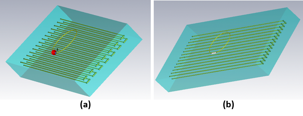
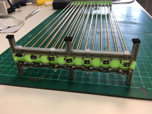
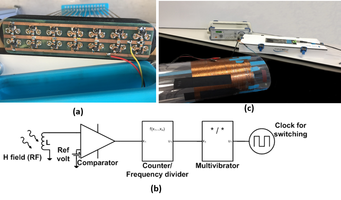
The metasurface consists of 2x14 wires rods (l=372mm and d=2mm) embedded in deionised water (Fig. 1)4. Each pair of adjacent wires was shorted both horizontally and vertically (Fig. 1) and the two setups were simulated. Results showed shorting horizontally demonstrated the desired resonance frequency shift. To validate the simulation, we have used a set of push button switches (Fig. 2) and measured the resonance frequency by turning them on and off simultaneously. For electronic tuning, MOSFETs operating at 10s of MHz were used. Although diodes are mainly used as switching elements, the significant advantage of MOSFETs is its reduced power consumption6. Inductors were used between gate and source of each MOSFET for biasing (Fig. 3 (a)). A digital electronic circuit converts a small (tens of mV) RF signal picked by the inductor to an R-R square wave by a comparator and then down-converts it by a 12-bit asynchronous counter (Fig. 3(b)). A monostable multivibrator down converts the output to a fixed frequency of ~10 kHz (~RC time-constant) with a duty cycle of more than 90%. A solenoid fed by an RF generator and an amplifier has been built to generate the desired magnetic field distribution (Fig 3(c)). The resonance frequency of the metasurface was measured by a loop antenna using a vector network analyser while turning on-off the RF source manually.Results and discussions
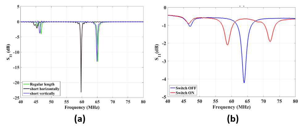
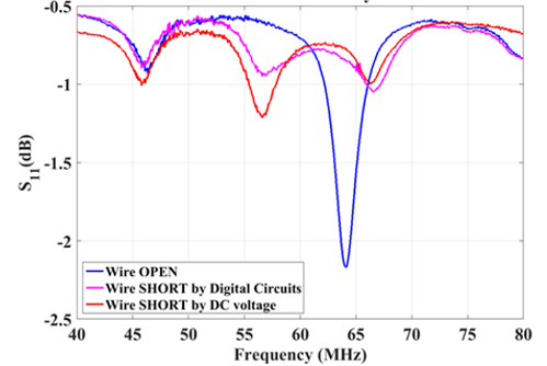
The simulated resonance frequency for shorting the metasurface resonator wire rods both horizontally and vertically clearly demonstrates that vertical shorting does not shift the resonance (Fig. 4 (a)). When shorted horizontally, the resonance shifts by approximately 5 MHz. The measured resonance frequency shift for the on-off state of the duel inline package (DIP) switches connected horizontally match the simulation results (Fig. 4(b)). For electronic tuning, 14 MOSFETs with inductors (3.3 µH) were used as the switching mechanism. The inductance produces a very small impedance (<1 Ohm) at DC and tens of kHz and thus, a very small voltage drop during actuation. The same inductance generates high-impedance (>300 Ohm) at 64 MHz, which would act like an open circuit and isolate the switches from each other. The gates were connected to a common bias line. There was no contact between the bias line and parallel wires, thus does not affect the resonance. Initially, a 3.3V DC was used to activate the MOSFETs directly and to detune the resonance frequency of the metasurface with voltage on-off (Fig. 5). Then, the digital circuit is used with an inductor to detect the magnetic field generated by a solenoid and an RF source. The digital circuits converted the small AC voltage picked by the inductor to an R-R wave of 3.3V at 10 KHz, which was used to activate the MOSFET circuits. Figure 5 shows the resonance of the metasurface resonator when the solenoid is turned on and off by switching the RF generator. It can be clearly seen for both for DC and RF generator that the resonance shifts by almost 5 MHz matching both simulation and DIP switches results. The switch matrix would enable the device to operate more efficiently by automatically detuning it at transmission, effectively cloaking its operation to avoid body overheating, and automatically tuning it back at receive mode, leading to significant enhancement of SNR and imaging quality of 1.5T MRI scans.Acknowledgements
This work was financially supported in part by Innovate UK under Projects 710771 & 102788.References
1. Khoo V S et al. Magnetic resonance imaging (MRI): considerations and applications in radiotherapy treatment planning, Radiotherapy and Oncology. 1997; 42(1):1-15.
2. S Lord S J et al. A systematic review of the effectiveness of magnetic resonance imaging (MRI) as an addition to mammography and ultrasound in screening young women at high risk of breast cancer, European journal of Cancer.2007; 43(13):1905-1917.
3. ASlobozhanyuk A P et al, Enhancement of Magnetic Resonance Imaging with Metasurfaces. Advanced Materials. 2016; 28(9):1832-1838.
4. Saha S C et al. Evaluation of metasurface resonator for in-vivo imaging at 1.5T. In proceeding of ISMRM 2017, HI, USA.
5. Burl M, Zou M X. Transmit mode coil detuning for MRI systems, Patent number: US6850067 B1, May 2003.
6. Reykowski A, Housen R. FET switches as detune circuits for MRI RF coils, Paten pub no: US 2014/0070808 A1, 2014.
Figures